Date created: Monday, March 30, 2020 4:18:29 PM. Last modified: Friday, January 12, 2024 5:49:18 PM
7750 SR Overview
References:
https://www.al-enterprise.com/-/media/assets/internet/documents/ale-nokia-7750-sr-s-service-router-ip-mpls-datasheet-en.pdf
http://gazettabyte.squarespace.com/home/2017/7/5/the-era-of-cloud-scale-routeing.html
https://documentation.nokia.com/cgi-bin/dbaccessfilename.cgi/3HE15815AAAATQZZA01_V1_7450%20ESS%207750%20SR%207950%20XRS%20and%20VSR%20Interface%20Configuration%20Guide%2020.2.R1.pdf
http://www.gazettabyte.com/home/2021/10/12/nokias-48-terabit-fp5-packet-processing-chipset.html
http://www.gazettabyte.com/home/2021/10/26/evolving-packet-processing-by-a-factor-of-1000.html
7750 Generations & Chassis
The original 7750-SR range was initially launched with the FP1 network processor, and later supported the FP2. The 7750 SR-e range initially supported the Nokia FP2 and later the FP3 network processor. The 7750 SR-s range was launched with the “highly programmable Nokia FP4 network processing (NP) silicon” and later supported the FP5.
A 7750 SR-12 supports 800Gbps FD non-redundant capacity or 400Gbps FD redundant capacity per slot.
A 7750 SR-12e supports 1.5Tbps FD non-redundant capacity or 1.2Tbps FD redundant capacity per slot.
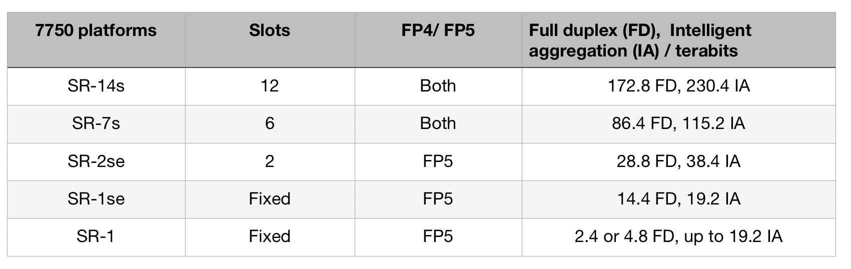
A 7750 SR-14s supports 4.8Tbps FD redundant capacity per slot.
Line Card Types
A 7750 chassis can contain various modules/line cards:
Switch Fabric Module (SFM),
Control Processor Module (CPM)
Input/Output Module (IOM/XIOM) and XMA Control Modules (XCM), XMA-s Control Module-s (XCM-s)
Media Dependent Adapter (MDA/MDA-e/MDA-e-XP), XRS Media Adapters (XMA), and Compact XMAs (C-XMA)
Integrated Services Adaptor for Multi-Service (MS-ISA), Multi-Service Integrated Services Module (MS-ISM)
Integrated Media Module (IMM)
eXpandable Media Adapters (XMA), eXpandable Media Adapters-s (XMA-s)
Switch Fabric Modules
The IOM3-XP has a T2 fabric engine, and the IOM3-XP-C has a T3 fabric engine. This means that the latter supports the faster fabric speeds used by FP3-based cards.
There are limitations on system capacity when mixing T2 and T3-based cards, there are also limitations on which line cards can be used. For example, a 7750 SR-12 with a SFM-5 fabric provides 100Gbps per slot of resilient capacity with a mixture of T2 and T3 cards, but 200Gbps per slot if all are T3-based. Note that FP4-based line cards cannot be used when T2 cards are present.
SF/CPM4 supports 1Tbps of resilient chassis fabric, 100Gbps per slot in a 7750 SR-12e.
SF/CPM5 supports 2Tbps of resilient chassis fabric, 200Gbps per slot in a 7750 SR-12 (subject to only having T3 linecards).
SF/CPM5 supports 4Tbps of resilient chassis fabric, 400Gbps per slot in a 7750 SR-12e (subject to only having T3 linecards).
SFM6/CPM5 supports 2.4Tbps of resilient fabric capacity, 260Gbps per slot in 7750 SR-12e.
SFM6/CPM5 supports 8Tbps of resilient fabric capacity, 800Gbps per slot in 7750 SR-12e (subject to only having T3 or T4 linecards).
The SFM-s is supported in the 7750-SRs chassis range.
Control Processor Modules
CPM-s and CPM-2s are supported in 7750-SRs chassis.
IOM/XIOM (Input/Output Module) and XMA Control Modules (XCM/XCM-s)
The forwarding complex is on the IOM (Input/Output Module).
7750 SR-7/12 and 7750 SR-12e platforms accept either IMMs or IOMs in card slots. IOMs have two slots for pluggable MDAs.
IOM, IOMB, and IOM2 include two 10G FP1 forwarding complexes and they all support two MDAs. Each FP1 corresponds to one of the two MDA slots providing 10Gbps FD capacity to each MDA.
An IOM2 supports 10Gb/s FD per MDA/sub-slot.
An IOM3-XP supports 25Gb/s FD / 50Gbps HD per MDA.
The IOM3-XP, IOM3-XP-B and IOM3-XP-C all have 2 sub-slots and all support MDA and MDA-XPs in each sub-slot. The IOM3-XP and IOM3-XP-B have a single FP2 forwarding engine and T2 fabric engine. The IOM3-XP-C has a T3 fabric engine. The FP2 is shared across all MDA slots. The 100G IOM3 (magma) is based on the FP2 and includes separate ingress & egress fp2 qchips each supporting 64k queues, all other FP2 & FP3 complexes support dynamic queues that are shared across the ingress and egress paths.
The IOM4-e is based on a single on the FP4 NPU and supports 200Gbps FD per-slot performance. The IOM4-e, IOM4-e-B, and IOM4-e-HS all support two MDA-e modules in the 7750 SR-7, 7750 SR-12, and 7750 SR-12e systems. Up to four MDA-e adapters are supported by the IOM-e in 7750 SR-e systems.
The IOM-s is based on two FP4 complexes and supports up to two MDA-s at up to 3.0Tbps FD.
The IOM5-e which is based on the Nokia FP4 and supports upto two MDA-e-XPs in the 7750 SR-7, SR-12 and the SR-12e. The 7750 SR-1 system has an integrated IOM5-e and supports up to two MDA-e-XPs. In the 7750 SR-12e it delivers up to 1.5 Tb/s FD (non-redundant) and 1.2 Tb/s FD (redundant) per-slot capacity. In the SR-7 and SR-12, it delivers up to 800 Gb/s FD (non-redundant) and up to 400 Gb/s FD (redundant) per-slot capacity. With iFIFO, the SR-12e supports up to 4.0 Tb/s FD per-slot capacity, and the SR-7 and SR-12 support up to 1.2 Tb/s FD per-slot capacity.
An XCM has two slots, each of which accept an XMA or C-XMA module. The C-XMA modules require a mechanical adapter to fit in an XMA slot.
The 7750 SR-2s/7s/14s platforms accept XCMs in card slots. The XCMs of the 7750 SR-2s/7s platforms have a single slot for an XMA or an XIOM module. The XCM of the 7750-14s have two slots for the XMA or XIOM modules. The 7750 SR-1s platform supports a single XCM in a dedicated card slot. This XCM has a single XMA module. The type of XMA module is fixed based on the variant of 7750 SR-1s chassis.
XIOM modules are modules that are used in 7750 SR-1s/2s/7s/14s platforms. These can be installed into an XCM instead of installing an XMA module. The XIOMs have two slots that support MDA-s modules (MDA-a, MDA-aXP, MDA, MDA-XP, MDA-e, and MDA-s). This allows an XCM in a 7750 SR-2s (for example) to contain MDAs by using the XIOM as a conversion module: the SR-2s could have upto two XCMs, each could contain upto two XMAs, providing four XMAs in total. Alternatively the SR-2s could have upto two XCMs, each could contain upto two XIOMs, and each XIOM could contain upto two MDAs, providing up to eight MDAs in total. Also a mixture of XCMs + XMAs and XCMs + XIOMs + MDAs can be used.
On the 7750 SR-1s/2s/7s/14s, the MDA-s modules are supported when an XIOM is installed.
Integrated Media Module (IMM)
IMMs have integrated MDAs.
The IMM48-1GB-SFP card which is 48x 1Gbps SFP ports consists of two fixed IMM24-1GB-XP-SFP MDA cards.
The IMM-2PAC-FP3 is a two MDA slot FP3 based card. p10-10g-sfp (10x10G ports) is an example MDA which could be inserted into an IMM-2PAC.
All FP2 based IMMs use a single FP2 chipset complex (except in the case of Magma IMMs) which is shared across all ports. The IMM48-GE card is an example FP2 based card (48x1GE ports).
For example, in an SR-12e with CPM5s, 400Gb/s (FD) per slot of switching capacity is available. But each MDA-e daughter card in an IOM-4 only has 100Gb/s of bandwidth so it's not possible to use the 400Gb/slot of capacity. Fixed cards (for example the 4x100GE IMMs) can use the full 400Gb/s of switching available.
Media Dependent Adapter / XRS Media Adapters
MDAs:
MDAs are pluggable adapter cards that provide physical interface connectivity. On 7750 SR-7/12, and 7750 SR-12e, MDAs plug into IOMs. On 7750 SR-7/12, and 7750 SR-12e platforms, MDA names in the CLI start with the letter 'm' (for example, m10-1gb-xp-sfp or m10-1gb-sfp). The 7750 SR-1e, 7750 SR-2e, and 7750 SR-3e support only MDA-e modules, which are identified in the CLI with an “me” prefix, such as me1-100gb-cfp2.
MDA/MDA-e/MDA-e-XP:
The MDA-e is based on the Nokia FP3 network processor and provides up to 100Gbps FD capacity. It is supported by the IOM4-e, IOM4e-B and IOM4-e-HS in the 7750 SR-7, SR-12 and SR-12e, and by the IOM-e in the 7750 SR-e series.
The MDA-e-XP provides up to 750Gb/s FD performance in a half-slot adapter. It is supported by the IOM5-e on the SR-1, SR-7, SR-12 and SR-12e.
The MDA-s supports up to 1.5 Tb/s FD in capacity and is supported in the 7750 SR-14s, SR-7s, SR-2s and SR-1s.
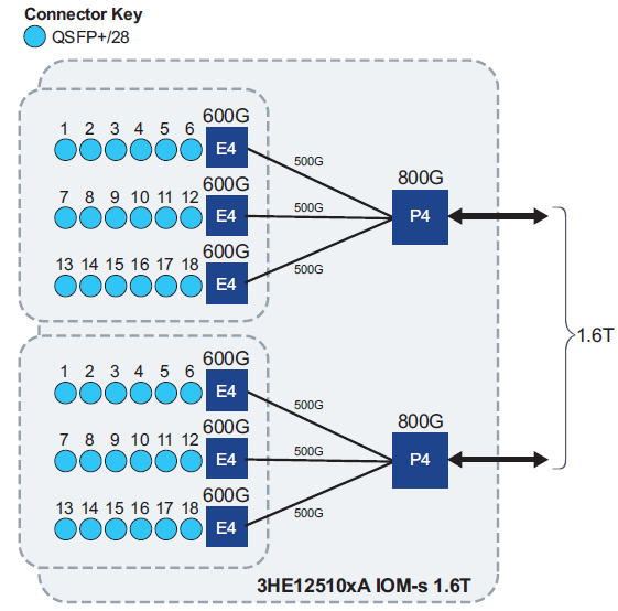
ms18-100g-qsfp28 is an 18x100G example of an MDA-s card. These are slightly oversubscribed as each group of 6 ports on the MDA is connected to an E4 chip which has a 500G connection to an FP, a ratio of 1.2:1.
MDA-s names in CLI start with the letters "ms" (for example, ms16-100g-sfpdd+4-100g-qsfp28).
XMAs:
XMAs are supported on the 7750 SR-1s/2s/7s/14s and 7950 XRS platforms. XMAs plug into XCMs. A maximum of two XMAs can be configured on an XCM.
The XCM and XMA were based on the FP3 chipset, newer generations use the FP4.
MDA and XMAs using an FP4 make use of the E-Chip which was introduced in the FP4 series of NPUs from Nokia.
Integrated Services Adaptor, Multi-Service Integrated Services Module
The MS-ISA (or ISA-MS in CLI) is an Integrated Services Adaptor for Multi-Service processing, as a resource module within the 7x50 system providing packet buffering and packet processing. MS-ISA can be used to implement CGN (Carrier Grade NAT) or LNS or BNG features. ISA-MS fits in an MDA/ISA slot on an IOM and has no external ports, so all communication passes through the IOM, making use of the network processor complex on the host IOM for queuing and filtering functions like other MDAs and ISAs.
The Nokia Multiservice Integrated Service Adapter 2 (MS-ISA2) is a general-purpose multicore processor based on the Nokia FP3 network processor. It delivers up to 40Gb/s of integrated service and application processing in a hot-swappable, half-slot form factor that inserts into an Input/Output Module 4-e (IOM4-e) and IOM-e.
The Multi-Service Integrated Services Module (MS-ISM) card contains two ISA2 processing modules providing increased packet processing throughput and scale compared to the MS-ISA platform. Each ISA2 processing module supports a 40Gbps datapath for packet processing; as with ISA1 the actual throughput varies by function. The IOM base card is an imm-2pac-fp3 with two embedded positions for ISA2s.
Combination IMMs support Ethernet ports and an embedded ISA2.
eXpandable Media Adapter
XMA-s uses an FP4 and supports interface speeds up to 400Gbps.
The XMA-s is housed in an XCM-s. The 7750 SR-s chassis use XCM-s to deliver 4.8 Tbps FD of per-slot capacity to a single XMA-s (e.g., 7750 SR-7s) or 9.6Tbps FD of per-slot capacity to larger chassis supporting two XMA-s per XCM-s (e.g., 7750 SR-14s).
Nokia NPUs
The common chips on Nokia cards are the Q-chip (the traffic manager), the P-chip (the packet processor), the T-chip (the fabric interconnect), and the E-chip (the MAC controller).
The q-chip is the traffic manager that oversees the packet flows and decides how packets should be dealt with, especially when congestion occurs. The p-chip network processor inspects packets and performs table look-ups using fast-access memory to determine where packets should be forwarded. The t-chip interfaces to the router fabric. In previous generations of router products a mid-plane was used. This has been replaced with switch fabric cards. The switch cards are held horizontally in the chassis and the line cards are vertical: “A bunch of metal guides are used to guide the two cards and they directly connect to each other...The t-chips are what interface to these connectors inside the system.” The E-chip acts as a media access controller (MAC) that parcels data from the router’s client-side pluggable optical modules for the P-chip, in later generations it also provides MACSec.
FP1
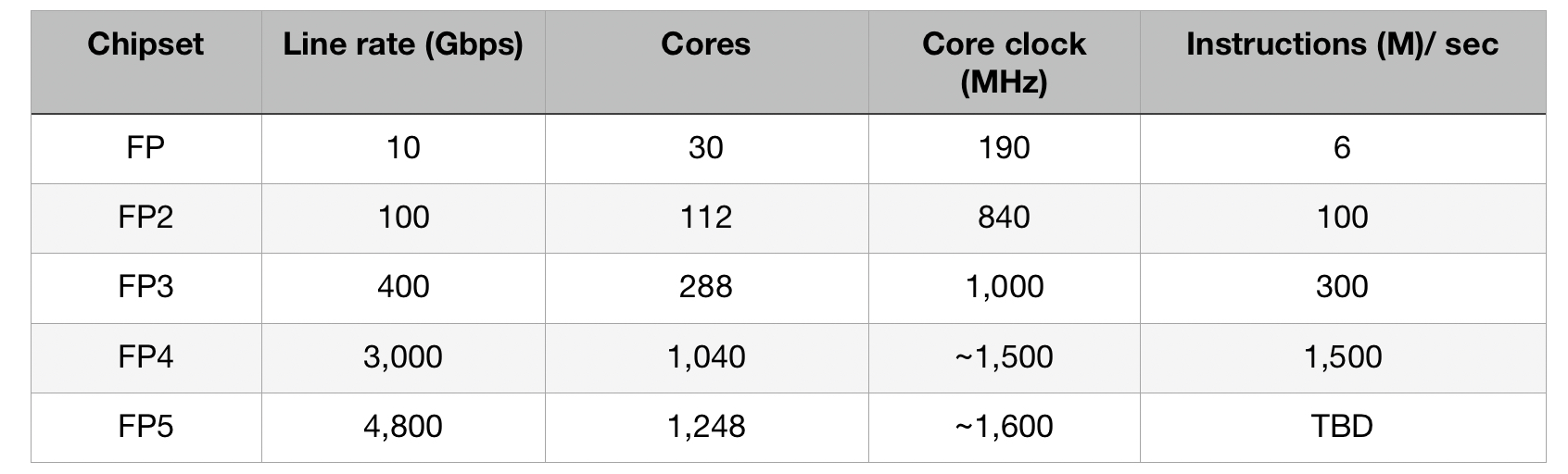
The FP1 was launched by Alcatel in 2003. The FP1 supported 10Gbps line rate and used 30 packet-processing cores that ran microcode, each core being clocked at 190MHz.
FP2
The ALU FP2 was launched in 2007. The FP2 supported 100Gbps and compared to the FP1 nearly quadrupled both the core count (112) and their clock rate (840MHz).
FP3
The FP3 was announced in 2011 by Alcatel-Lucent before they were acquired by Nokia in 2016, and supports 400Gbps.
The FP3 network processor chipset is comprised of three chip types: the P-chip, the Q-chip, and the T-chip (some have 2x P-chips and a single Q-chip, some also have an S-chip which is a switch IC that was later combined with the T-chip in the FP4). The FP3 uses 10Gbps SerDes.
The FP3s P-chip uses 288 programmable cores. Each programmable core can process two instructions per clock cycle and is clocked at 1GHz. The 288 cores are arranged as a 32-row-by-9-column 2D array. Each row of cores can be viewed as a packet-processing pipeline. Each pipeline could be partitioned to perform independent tasks. The array’s columns perform table look-ups and each column could be assigned several tasks.
The FP3’s traffic manager (the Q-chip) comprises four reduced instruction set computer (RISC) cores clocked at 900MHz.
FP4
The FP4 is a 2.4Tbps network processor that had 6x the throughput of the existing FP3, but the FP4 was later bumped up to 3Tbps, 7.5x the FP3.
The FP4 is a four-IC chipset implemented using 16nm CMOS FinFET technology. Nokia skipped 28nm and 22nm CMOS nodes and went from 40nm CMOS for the FP3, to 16nm FinFET for the FP4.
To maximise the memory performance, Nokia used advanced packaging for the FP4’s P-chip and Q-chip. Each memory stack comprises 5 memory die. All of these sit on an interposer substrate, itself a die, that is used for dense interconnection of devices. The resulting FP4 p-chip is thus a 22-die multi-chip module “Our memory stacks are connected at the die edges and do not use through-silicon vias...hence it is technically a 2.5D package [rather than 3D].” Two of the four devices in the FP4 chipset are multi-chip modules (the P-chip and the Q-chip). The resulting 2.5D-packaged P-chip comprises the packet processor die and stacks of memory. The q-chip module contains RISC processors and buffering memory.
The FP4 uses 1,040 cores, each executing two instructions per clock cycle. The die-shrink allowed the cores to be clocked at 1.5GHz and hyper-threading was added.
Nokia claims to have developed its own “smart memory” for the FP4 which can “perform a task that otherwise would require multiple memory accesses, thereby adding much-needed parallelism.” This is required for counters/look-ups which need very high-speed memory that supports 32-bit and 64-bit reads and writes. Four “smart memory” dies are included in the FP4’s P-chip, and for buffering four high-bandwidth memory (HBM) blocks, each comprising stacked memory die, are part of the Q-chip.
“All chipsets released prior to the FP5 make use of HBM2 and are constrained to a maximum of some 1.7Tbps of full-duplex bandwidth to buffer memory…The FP4's HBM2 buffer memory supports a 1.5Tbps linerate”.
In addition, the FP4 uses 56Gbps serialiser-deserialiser (serdes) from Broadcom, implemented using PAM-4 modulation.
In the FP4 Nokia had a pre-standard implementation of FlexMAC implemented in the E-chip, why???
The 7750 Service Router (SR-s) edge router family supports up to 144Tbps in a single shelf. This highest capacity configuration is the 7750 SR-14. It is a 24RU + power-supply high chassis, and supports 21 linecards, each at 12Tbps FD / 27Tbps HD when using 100-gigabit modules, or 24x400GbE when using QSFP-DD modules.
FP5
The FP5 uses a 7nm CMOS process technology and provides 4.8Tbps of forwarding capacity, native 100Gbps SERDES rates, and uses 75 percent less power than the FP4. Nokia FP5s combined on-chip what were separate chips on the FP4: the P-chip (the packet processor), the Q-chip (the traffic manager) and the T-chip (the fabric interconnect). This means that whereas the FP4 was a 4-chip chipset, the FP5 is a 3-chip chipset (the main P/Q/T-chip, the S-chip, and the E-chip).
The lower power consumption of the FP5 chipset compared to the FP4 (0.1W per Gbps vs. 0.4W per Gbps) comes partially from consolidating the two chips into one, using 112Gbps SERDES is another part, and a more advanced CMOS process also contributes.
The FP5 uses the same “smart memory” which is used in the FP4, but this time on-chip, freeing up room for the latest HBM2e technology for packet buffering. “This allows us to get the speeds we need…So when we say we have a 14.4-terabit card, it allows true QoS (quality of service) on every packet…All chipsets released prior to the FP5 make use of HBM2…whereas HBM2e [in FP5s] can support 2.4Tbps linerate”.
FP5s are backward compatible with the FP4 and can be mixed with FP4 based line cards in the same chassis without limitation, meaning that FP4s and FP5s in the same chassis can both run at line rate. FP5’s can also be run with FP3s, the FP5 can implement the FP3’s instruction set, but the FP5 also includes newer instructions. In one clock cycle, multiple instructions can be executed in an FP5. The FP5 also supports multithreading that did not exist with the FP3, meaning that several instruction threads are interleaved and processed in parallel.
The E-chip has also been upgraded in the FP5 to support line-rate MAC-Sec. It now also acts as an early-stage packet processor, performing pre-processing, pre-classification, and pre-buffering tasks on the traffic. Using multiple such devices allows the line card to expand the forwarding limit of the FP5’s packet processor. “We use multiple e-chips in front of our packet processor to allow the faceplate of our card to expand in terms of port capabilities beyond the forwarding limit of our packet processor”. Nokia claims that this enables Nokia’s routers to perform what Nokia call “intelligent aggregation” or IA: “We can bring in more traffic, increase the number of ingress ports even if those ports start to get fully loaded, because of the chipset architecture being fully buffered…The result is a 30 percent uplift in the stated capacity numbers”.
Nokia explain: “It goes well beyond basic oversubscription because we pre-buffer and pre-classify to ensure that high priority traffic is always guaranteed..This is different from classic oversubscription where, when the given rate for a packet processor is exceeded, the next packet is by default discarded, irrespective of QoS…It means we can flexibly offer more ports on the faceplate of a card to satisfy increasing port requirements without fear of indiscriminate packet drops”.
Example Systems
7750 SR-12 example:
- A 7750 SR-12 has 10 slots.
- Each slot can contain an IOM (or fixed format IMM). An IOM has two sub-slots.
- MDA (media adapters) fit into the IOM slots.
- An IOM contains a forwarding complex responsible for queuing, processing, and forwarding of data. It also has a control CPU and memory, and a fabric interface. The MDA only contains media-specific functionality. For example, an ethernet or SONET framer.
- An IMM is a fixed line card, like an IOM but with MDAs permanently attached.
- XMAs (eXpandable Media Adapters) contain an FP forwarding complex and use front faceplate connectors for optical modules.
- XCMs (XMA Control Modules) is where the XMA is housed. The XCM-s contains a slot-level control plane subsystem and fabric interface.
The ports on a 7750 are numbered as follows:
Port 3 on MDA 1 in an IOM in slot 1 would be port 1/1/3
Port 3 on MDA 2 in an IOM in slot 1 would be port 1/2/3
Example 7750 SR-12 with FP3s:
*A:sr10# show card

===============================================================================
Card Summary
===============================================================================
Slot      Provisioned Type                         Admin Operational   Comments
              Equipped Type (if different)         State State
-------------------------------------------------------------------------------
1         imm-2pac-fp3                             up    up
2         imm-2pac-fp3                             up    up
3         imm-2pac-fp3                             up    up
5         iom4-e                                   up    up
6         iom4-e                                   up    up
7         imm-2pac-fp3                             up    up
8         imm-2pac-fp3                             up    up
9         imm-2pac-fp3                             up    up
10        imm-2pac-fp3                             up    up
A         cpm5                                     up    up/active
B         cpm5                                     up    up/standby
===============================================================================

*A:sr10# show mda

===============================================================================
MDA Summary
===============================================================================
Slot  Mda   Provisioned Type                            Admin     Operational
                Equipped Type (if different)            State     State
-------------------------------------------------------------------------------
1     1     p6-10g-sfp                                  up        up
      2     p6-10g-sfp                                  up        up
2     1     p6-10g-sfp                                  up        up
      2     p6-10g-sfp                                  up        up
3     1     p10-10g-sfp                                 up        up
      2     p1-100g-cfp                                 up        up
5     1     me10-10gb-sfp+                              up        up
      2     me2-100gb-qsfp28                            up        up
6     1     me10-10gb-sfp+                              up        up
      2     me2-100gb-qsfp28                            up        up
7     1     p10-10g-sfp                                 up        up
      2     p1-100g-cfp                                 up        up
8     1     p10-10g-sfp                                 up        up
      2     p1-100g-cfp                                 up        up
9     1     p10-10g-sfp                                 up        up
      2     p1-100g-cfp                                 up        up
10    1     p6-10g-sfp                                  up        up
      2     p6-10g-sfp                                  up        up
===============================================================================
7750 SR-2s Example:
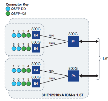
7750 SR-2s routers accept 2x XCM cards or 2x IOM-s cards. Each XCM can accept 1x XMA or 1x XIOM. Each IOM-s card accepts 2x MDA-s cards. An example is to use the xcm-2s cards, each containing 1x IOM-s card (iom-s-3.0t:he1600g+), each with 2x MDAs (ms18-100gb-qsfp28). These MDAs are 18x connectors of QSFP28 at 1.2 Tbbps FD with 1x FP4 complex. XMAs are the all-in-one cards which are not used here:
*B:bs1# show card state

=================================================================
Card State
=================================================================
Slot/  Provisioned Type                  Admin Operational   Num   Num Comments
Id         Equipped Type (if different)  State State         Ports MDA
-------------------------------------------------------------------------------
1      xcm-2s                            up    up                  1     <- XCM
1/x1   iom-s-3.0t:he1600g+               up    up                        <- XIOM
1/x1/1 ms18-100gb-qsfp28                 up    up            18          <- MDA
1/x1/2 ms18-100gb-qsfp28                 up    up            18          <- MDA
2      xcm-2s                            up    up                  1
2/x1   iom-s-3.0t:he1600g+               up    up
2/x1/1 ms18-100gb-qsfp28                 up    up            18
2/x1/2 ms18-100gb-qsfp28                 up    up            18
A      cpm-2s                            up    up                      Standby
B      cpm-2s                            up    up                      Active
=================================================================


*B:bs1# show datapath 1

===============================================================================
Card    [XIOM/]MDA  FP        MAC Chip Num   Connector      Port
-------------------------------------------------------------------------------
1       x1/1        1         1              c1
1       x1/1        1         1              c2
1       x1/1        1         1              c3
1       x1/1        1         1              c4
1       x1/1        1         1              c5
1       x1/1        1         1              c6
1       x1/1        1         2              c7
1       x1/1        1         2              c8
1       x1/1        1         2              c9
1       x1/1        1         2              c10
1       x1/1        1         2              c11
1       x1/1        1         2              c12
1       x1/1        1         3              c13
1       x1/1        1         3              c14
1       x1/1        1         3              c15
1       x1/1        1         3              c16
1       x1/1        1         3              c17
1       x1/1        1         3              c18
1       x1/2        2         1              c1
1       x1/2        2         1              c2
1       x1/2        2         1              c3
1       x1/2        2         1              c4
1       x1/2        2         1              c5
1       x1/2        2         1              c6
1       x1/2        2         2              c7
1       x1/2        2         2              c8
1       x1/2        2         2              c9
1       x1/2        2         2              c10
1       x1/2        2         2              c11
1       x1/2        2         2              c12
1       x1/2        2         3              c13
1       x1/2        2         3              c14
1       x1/2        2         3              c15
1       x1/2        2         3              c16
1       x1/2        2         3              c17
1       x1/2        2         3              c18
===============================================================================
Previous page: 7210 SAS-X Overview
Next page: Show Egress MPLS Label Stack