Date created: Wednesday, April 24, 2019 7:34:12 AM. Last modified: Sunday, December 3, 2023 4:49:02 PM
Ethernet OAM and CFM Standards
References
https://www.cisco.com/c/en/us/td/docs/ios-xml/ios/cether/configuration/12-2sr/ce-12-2sr-book/ce-oam.html
http://www.ieee802.org/3/efm/public/jul03/oam/efm_oam_tutorial_2003_07_23.pdf
https://www.cisco.com/c/en/us/td/docs/solutions/Enterprise/WAN_and_MAN/Ethernet_Access_for_NG_MAN_WAN_V3-1_external.html
https://wiki.mef.net/display/CESG/ITU-T+Y.1731+Reference+Page
https://www.fujitsu.com/downloads/TEL/fnc/whitepapers/EthernetService-OAM.pdf
https://www.itu.int/rec/dologin_pub.asp?lang=e&id=T-REC-G.8013-201508-I!!PDF-E&type=items
Quick Comparison
The following protocols are the building blocks for Ethernet OAM:
- IEEE 802.1ag: Connectivity Fault Management (CFM)
- ITU-T (G.8013) Y.1731: OAM functions and mechanisms for Ethernet-based networks
- IEEE 802.3ah: Ethernet Link OAM (EFM OAM)
- MEF-16 E-LMI: Ethernet Local Management Interface
IEEE 802.3ah EFM (Ethernet in the First Mile) OAM
Ethernet OAM PDUs:
OAM frames, called OAM Protocol Data Units (PDUs), use the slow protocols destination MAC address 01:80:c2:00:00:02 and slow protocols Ethertype value 0x8809. OAM PDUs are standard length, untagged Ethernet frames within the normal frame length bounds of 64 to 1518 bytes. The maximum OAM PDU frame size exchanged between two peers is negotiated during the discovery phase.
The OAM PDUs are intercepted by the MAC sublayer and cannot propagate beyond a single hop within an Ethernet network (by a switch or bridge). This effectively makes the technology link-local OAM.
Ethernet OAM is a relatively slow protocol with modest bandwidth requirements. The frame transmission rate is limited to a maximum of 10 frames per second; therefore, the impact of OAM on normal operations is negligible. Some OAM PDU types may be transmitted multiple times to increase the likelihood that they will be successfully received on a deteriorating link.
Ethernet OAM interworks or is relayed to CFM on the same device. CFM can then notify remote devices of the localised fault, as previously described.
OAM Features and Frame Types:
The OAM features as defined by IEEE 802.3ah, Ethernet in the First Mile, are Discovery, Link Monitoring, Remote Fault Detection and Remote Loopback. Optionally vendors can implement vendor proprietary extensions. Each of the four features uses one of the four different kind of OAM PDUs.
Discovery:
Discovery is the first phase of Ethernet OAM and it identifies the devices in the network and their OAM capabilities. Discovery uses Information OAM PDUs which are variable-length OAM PDUs that include local, remote, and organization-specific information. During the discovery phase, the following information is advertised within periodic information OAM PDUs:
OAM mode: Conveyed to the remote OAM entity. The mode can be either active or passive and can be used to determine device functionality.
OAM configuration (capabilities): Advertises the capabilities of the local OAM entity. With this information a peer can determine what functions are supported and accessible; for example, loopback capability.
OAM PDU configuration: Includes the maximum OAM PDU size for receipt and delivery. This information along with the rate limiting of 10 frames per second can be used to limit the bandwidth allocated to OAM traffic.
Platform identity: A combination of an organization unique identifier (OUI) and 32-bits of vendor-specific information. OUI allocation, controlled by the IEEE, is typically the first three bytes of a MAC address.
Discovery includes an optional phase in which the local station can accept or reject the configuration of the peer OAM entity. For example, a node may require that its partner support loopback capability to be accepted into the management network. These policy decisions may be implemented as vendor-specific extensions.
Link Monitoring:
Link monitoring in Ethernet OAM detects and indicates link faults under a variety of conditions. Link monitoring uses the event notification OAM PDU and sends events to the remote OAM entity when there are problems detected on the link. These are a variable-length OAM PDU that may be transmitted multiple times to increase the chance of a successful receipt; for example, in the case of high-bit errors. Event notification OAM PDUs also may include a time stamp when generated.
The error events signaled with event notification OAM PDUs include the following:
Error Symbol Period (error symbols per second): The number of symbol errors that occurred during a specified period exceeded a threshold. These errors are coding symbol errors.
Error Frame (error frames per second): The number of frame errors detected during a specified period exceeded a threshold.
Error Frame Period (error frames per n frames): The number of frame errors within the last n frames has exceeded a threshold.
Error Frame Seconds Summary (error seconds per m seconds): The number of error seconds (1-second intervals with at least one frame error) within the last m seconds has exceeded a threshold.
Since IEEE 802.3ah OAM does not provide a guaranteed delivery of any OAM PDU, the event notification OAM PDU may be sent multiple times to reduce the probability of a lost notification. A sequence number is used to recognize duplicate events.
Remote Failure Indication:
Faults in Ethernet connectivity that are caused by a gradual deterioration in quality are difficult to detect. Ethernet OAM provides a mechanism for an OAM entity to convey these failure conditions to its peer via specific flags in either the information OAM PDU or a vendor specific extension PDU. The following failure conditions can be communicated:
Link Fault: Loss of signal is detected by the receiver; for instance, the peer's laser is malfunctioning. A link fault is sent once per second in the information OAM PDU. Link fault applies only when the physical sublayer is capable of independently transmitting and receiving signals.
Dying Gasp: An unrecoverable condition has occurred; for example, a power failure. This type of condition is vendor specific. A notification about the condition may be sent immediately and continuously.
Critical Event: An unspecified critical event has occurred. This type of event is vendor specific. A critical event may be sent immediately and continuously (this can exceed the 10fps limit in the protocol standard).
Remote Loopback:
An OAM entity can put its remote peer into loopback mode using the loopback control OAM PDU. These OAM PDUs are fixed at 64 bytes in length and used to enable or disable the remote loopback feature. Loopback mode helps an administrator ensure the quality of links during installation or when troubleshooting. In loopback mode, every frame received is transmitted back on the same port except for OAM PDUs and pause frames. The periodic exchange of OAM PDUs must continue during the loopback state to maintain the OAM session.
The loopback command is acknowledged by responding with an information OAM PDU with the loopback state indicated in the state field. This acknowledgement allows an administrator, for example, to estimate if a network segment can satisfy a service-level agreement. Acknowledgement makes it possible to test delay, jitter, and throughput.
When an interface is set to the remote loopback mode the interface no longer participates in any other Layer 2 or Layer 3 protocols; for example, Spanning Tree Protocol (STP) or Open Shortest Path First (OSPF). The reason is that when two connected ports are in a loopback session, no frames other than the OAM PDUs are sent to the CPU for software processing. The non-OAM PDU frames are either looped back at the MAC level or discarded at the MAC level.
From a user's perspective, an interface in loopback mode is in a link-up state.
Vendor-Specific Extensions:
Ethernet OAM allows vendors to extend the protocol by allowing them to create their own type-length-value (TLV) fields. These TLVs are sent in vendor specific OAM PDUs.
MEF-16 E-LMI (Ethernet Local Management Interface)
E-LMI frames use the destination MAC address 01:80:C2:00:00:07. The E-LMI Ethertype is 0x88EE. The source MAC address is the sending port MAC.
Note: Use of the address (01:80:C2:00:00:07) requires that there is no 802.1Q complaint component between UNI-C and UNI-N.
There are only two types of E-LMI frame, Status and Status Enquiry.
IEEE 802.1ag Ethernet CFM (Connectivity Fault Management)
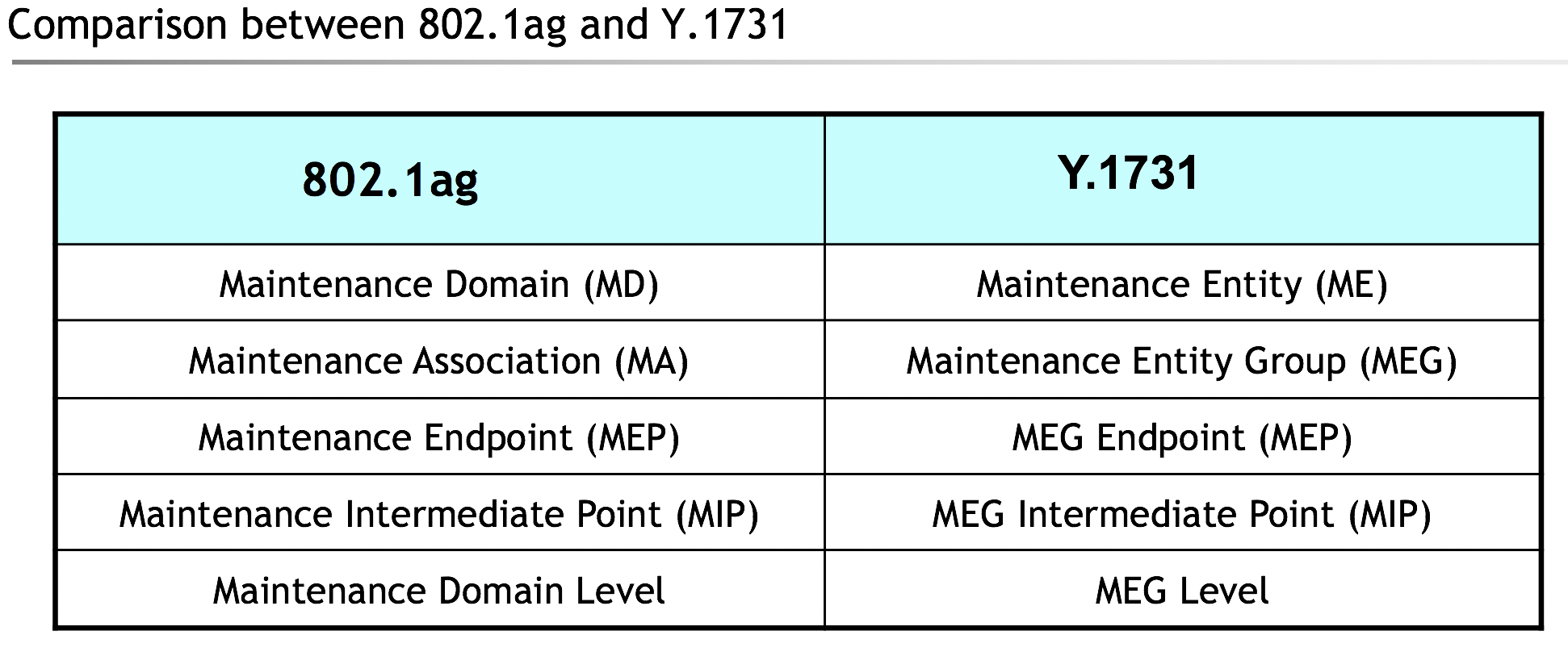
IEEE 802.1ag is an amendment to IEEE 802.1Q-2005 and was approved in 2007. Both 802.1Q and Y.1731 define a fault management capability. Their OAM fault management definitions are almost identical, the primary difference is some of the terminology.
Ethernet Connectivity Fault Management (CFM) is an end-to-end per-service-instance Ethernet layer OAM protocol that includes proactive connectivity monitoring, fault verification, reporting and fault isolation. End to end can be provider edge (PE) to PE or customer edge (CE) to CE. Per service instance means per VLAN. In MEF terminology CFM can operate per Ethernet Virtual Connection (EVC, e.g. E-Line, E-LAN or E-Tree) or per Operator Virtual Connection (OVC, e.g. E-Access).
CFM uses the destination multicast MAC address range 01:80:C2:00:00:30 through 01:80:C2:00:00:3F. The Ethertype used is 0x8902.
OpCodes indicate the OAM message type e.g. Continuity Check, Loopback, etc. OpCodes 0 - 31 are assigned by IEEE 802.1. Continuity Check, Loopback, and Link Trace use OpCodes in this range, and the OpCode assignments are the same for Y.1711 and 802.1ag. OpCodes 32 - 63 are assigned by ITU SG 13. Performance Management functions, which are only supported in Y.1731, fall into this range. OpCodes 64 - 255 are assigned by IEEE 802.1.
Ethernet CFM runs over bridged networks in the Ethernet service layer, as opposed to link layer OAM that is specified by IEEE 802.3 for cases where the link is Ethernet.
IEEE 802.1ag and ITU-T Y.1731 define joint constructs and terminology. It enables defining levels of hierarchical administrative domains, performing the CFM procedures within each domain independently.
The following procedures and packet formats are defined:
Continuity Check Messages (CCM) - MEPs periodically exchange Continuity Check OAM messages to detect loss of continuity or incorrect network connections. A CCM is multicast to each MEP in a MA/MEG at each administrative level. CC Messages can also be used to perform two way dual-ended Frame Loss measurements. A Flags field is incorporated in CC Messages. This field includes a bit for Remote Defect Indication (RDI) and an indication of the period at which CC Messages are transmitted.
Loopback Message (LBM) - MEPs send loopback messages to verify connectivity with another MEP or MIP for a specific MA/MEG. Loopback is a ping-like request/reply function. A MEP sends a loopback request message to another MEP or MIP, which generates a subsequent LRM. LBMs/LRMs are used to verify bidirectional connectivity. They are typically initiated by operator command. However, a MEP can be provisioned to send LBMs periodically. For IEEE 802.1ag, loopback is a unicast OAM message. Y.1731 allows both unicast and multicast loopback.
Link Trace Message (LTM) - MEPs multicast LTMs on a particular MA/MEG to identify adjacency relationships with remote MEPs and MIPs at the same administrative level. LTM can also be used for fault isolation. The message body of an LTM includes a destination MAC address of a target MEP that terminates the linktrace. When a MIP or MEP receives an LTM, it generates a unicast LTR to the initiating MEP. It also forwards the LTM to the target MEP destination MAC address. An LTM effectively traces the path to the target MEP.
Alarm Indication Signal (AIS) - When an MEP detects a connectivity failure at level N, it will multicast AIS in the direction away from the detected failure at the next most superior level. It will multicast AIS on each S-VLAN affected by the failure. AIS serves two purposes: 1) alarm suppression so that an NMS does not receive an excessive number of redundant alarms for a particular fault; 2) Informs clients that a transport path and/or a service instance has failed. For point-to-point S-VLANs/Ethernet connections, there is only one remote peer MEP that cannot be reached. However, for multipoint S-LANs/Ethernet connections, a client layer MEP, upon receiving an AIS, cannot determine which of its remote peers have lost connectivity. It is recommended that for multipoint the client layer MEP should suppress alarms for all peer MEPs. Use of AIS is not recommended for environments that utilize the spanning tree protocol, which provides an independent restoration capability. Due to the spanning tree and multipoint limitation associated with AIS, IEEE 802.1 committee has chosen not to support AIS in 802.1ag.
Remote Defect Indication (RDI) - When a downstream MEP detects a defect condition, such as receive signal failure or AIS, it will send an RDI in the opposite upstream direction to its peer MEP(s). This informs the upstream MEPs that there has been a downstream failure. RDI is subject to the same multipoint issue as AIS. A MEP that receives an RDI cannot determine what subset of peer MEPs have experienced a defect. For Y.1711, RDI is encoded as a bit in the Flags field in CC messages. IEEE 802.1ag does not support RDI.
ITU-T (G.8013) Y.1731: OAM functions and mechanisms for Ethernet-based networks
ITU-T Y.1731 augments IEEE 802.1ag in defining capabilities to perform Performance Monitoring (PM) for Ethernet services. It also provides additional Fault Management (FM) capabilities. Y.1731 defines the frame format and multicast addresses to be used for both PM and FM.
Continuity check (CCM), loopback (LBM/LBR), link trace Link trace (LTM/LTR) are remote defect indication (RDI) are defined in IEEE 802.1ag CFM; in additional to these ITU-T Y.1731 defines may more procedures and frame formats for Fault Management:
- Ethernet Continuity Check (ETH-CC): Present in IEEE802.1ag
- Ethernet Loopback (ETH-LB): Present in IEEE802.1ag
- Ethernet Link Trace (ETH-LT): Present in IEEE802.1ag
- Ethernet Alarm Indication Signal (ETH-AIS): Present in IEEE802.1ag
- Ethernet Remote Defect Indication (ETH-RDI): Present in IEEE802.1ag
- Ethernet Locked Signal (ETH-LCK): Locked Signal is transmitted by a MEP to communicate intentional administrative or diagnostic actions at that MEP. LCK is sent to all associated client layer (layer N+1) MEPs. It is used for client layer alarm suppression and enables client MEPs to differentiate between the defect conditions and intentional administrative/diagnostic actions at the server layer MEP.
- Ethernet Test Signal (ETH-Test): A MEP sends an OAM message that includes test data, which can be used to test throughput, measure bit errors, or detect frames delivered out of sequence. The test data can be configured to be a pseudorandom sequence or a test pattern. The test function is one way only and can be accomplished either in service or out of service.
- Ethernet Automatic Protection Switching (ETH-APS): The Ethernet automatic protection switching function (ETH-APS) is used to control protection switching operations to enhance reliability.
- Ethernet Maintenance Communication Channel (ETH-MCC): MCC provides a maintenance communications channel between a pair of MEPs. This channel can be used to perform remote maintenance, such as requesting remote maintenance from a peer MEP. Specific applications and the protocol for the MCC are not defined. The PDU includes an OUI, which encodes an organization specific use of the MCC.
- Ethernet Experimental (ETH-EXP) and Vendor-Specific (ETH-VSP): Vendor Specific and Experimental OAM (VSM and VSR/EXM and EXR) – Y.1731 has reserved two of its OpCode points for Vendor Specific and Experimental OAM frames. Vendor Specific allows for vendor value add Ethernet OAM extensions. Experimental allows for functionality, which can be used within an administrative domain on a temporary basis. Both of these OAM frame types include an OUI field to identify a specific vendor or administration.
- Ethernet Client Signal Fail (ETH-CSF): The Ethernet client signal fail function (ETH-CSF) is used by a MEP to propagate to a peer MEP the detection of a failure or defect event in an Ethernet client signal when the client itself does not support appropriate fault or defect detection or propagation mechanisms such as ETH-CC or ETH-AIS. The ETH-CSF messages propagate in the direction from the Ethernet MEP, associated with the ingress client port detecting the failure or defect event, to the Ethernet peer MEP. ETH-CSF is only applicable to point-to-point Ethernet transport applications. In particular, the use of ETH-CSF with [IEEE 802.1Q] or other Ethernet Spanning Tree Protocol (STP)-based networking environments is strictly restricted to point-to-point segments of the Ethernet flow.
- Ethernet bandwidth notification (ETH-BN): The Ethernet Bandwidth Notification function (ETH-BN) is used by a server MEP to signal the server layer link bandwidth in the transmit direction to a MEP at the client layer, for example when the server layer runs over a microwave link which has the capability to adapt its bandwidth according to the prevailing atmospheric conditions. Frames with ETH-BN information carry the current and nominal bandwidth of the server layer link. On receiving frames with ETH-BN information, the client layer MEP can use bandwidth information to adjust service policies, e.g. to reduce the rate of traffic being directed towards the degraded link.
- Ethernet expected defect function (ETH-ED): The Ethernet expected defect function (ETH-ED) is used by a MEP to signal to its peer MEPs that transmission of CCM frames is expected to be interrupted, without any interruption to data frames, and that the consequent loss of continuity defects at the peer MEPs should therefore be suppressed. Frames with ETH-ED information carry the MEP ID of the MEP and the expected duration of the interruption.
OAM frames and functions for Performance Monitoring:
- Ethernet Frame Loss Measurement (ETH-LM): FLR (Frame Loss Ratio) is defined as a ratio, expressed as a percentage, of the number of service frames not delivered divided by the total number of service frames during time interval T, where the number of service frames not delivered is the difference between the number of service frames sent to an ingress UNI and the number of service frames received at an egress UNI. Two types of FLR measurement are possible, Dual-ended LM and Single-ended LM. Dual-ended LM is accomplished by exchanging CCM OAM frames that include appropriate counts of frames transmitted and frames received. These counts do not include OAM frames at the MEPs ME Level. Dual-ended LM enables the proactive measurement of both Near End and Far End FLR at each end of a MEG. Single-ended LM is accomplished by the on-demand exchange of LMM and LMR OAM frames. These frames include appropriate counts of frames transmitted and received. Single-ended LM only provides Near End and Far End FLR at the end that initiated the LM Request.
- Ethernet Frame Delay Measurement (ETH-DM): FD (Frame Delay) is specified as round trip delay for a frame, where FD is defined as the time elapsed since the start of transmission of the first bit of the frame by a source node until the reception of the last bit of the loop backed frame by the same source node, when the loopback is performed at the frame's destination node.
- Ethernet Frame Delay Variation (FDV): FDV is a measure of the variations in the FD between a pair of service frames, where the service frames belong to the same CoS instance on a point-to-point Ethernet connection. There are two types of FD measurements, One-way and Two-way. One-way FD is measured by MEPs periodically sending 1DM frames, which include appropriate Transmit Time Stamps. FD is calculated at the receiving MEP by taking the difference between the Transmit Time Stamp and a Receive Time Stamp, which is created when the 1DM frame is received. One-way DM requires synchronized clocks between the two MEPs. Two-way DM measures round trip delay and does not require synchronized clocks. It is accomplished by MEPs exchanging DMM and DMR frames. Each of these DM OAM frames includes Transmit Time Stamps. Y.1731 allows an option for inclusion of additional time stamps such as a Receive Time Stamp and a return Transmit Time Stamp. These additional time stamps compensate for DMR processing time. FDV is calculated exactly as the difference between two consecutive Two-way FD measurements.
-
Throughput measurement: Throughput is the average rate of successful traffic delivery over a communication channel. This is typically measured under test conditions, i.e., an out-of-service test, where there is no service traffic for the Ethernet service under test. ITU-T Y.1564 defines a methodology to test Ethernet-based services at the service activation stage, using an out-of-service test. The Recommendation describes service configuration tests to verify bandwidth profiles and other Ethernet service attributes. Procedures used for out-of-service testing other than for Ethernet service activation can also be found in IETF RFC 2544. The procedure for in-service testing is out of scope of ITU-T Y.1731.
ITU-T Y.1731 PDUs
The Ethertype used for ITU-T Y.1731 OAM PDU frames is 0x8902, the same as IEEE 802.1ag CFM OAM PDUs.
Some messages use a unicast MAC destination address, and some use a reserved multicast destination address, which is treated as L2CP traffic. The MAC source address is always a unicast address.
The two types of frames, Class 1 and Class 2:
- Class 1, used for example by CCM, uses a MAC destination address of 01:C2:80:00:00:3x with x being in the range from 0 to 7, where the MEG level is represented by x.
- Class 2, used by LBM and LTM for example, uses a MAC destination address of 01:C2:80:00:00:3y with y being in the range from 8 to F, where the MEG level +8 is represented by y.
In addition, a specific range of multicast destination addresses with ITU OUI (01:19:A7) is used for Ring APS frames.
For multicast, the MAC destination address is defined as follows depending on the type of OAM function:
- Multicast Destination Class 1: OAM frames that are addressed to all peer MEPs in a MEG (e.g., CCM, Multicast LBM, AIS, etc.).
- Multicast Destination Class 2: OAM frames that are addressed to all MIPs and peer MEPs in a MEG (e.g., LTM).
- Multicast Destination for Ring APS: OAM frames used for Ethernet ring protection.
Diagrams
Previous page: Copper Connectors
Next page: Interop MTUs