Date created: Thursday, August 11, 2016 1:39:09 PM. Last modified: Monday, July 13, 2020 11:12:21 AM
Nexus 7000 with F Cards
References:
http://www.cisco.com/c/en/us/products/collateral/switches/nexus-7000-series-switches/data_sheet_c78-685394.html
http://www.cisco.com/c/en/us/products/collateral/switches/nexus-7000-series-switches/data_sheet_c78-684211.html
BRKRST-2930 - Implementing QoS with Nexus and NX-OS
http://www.cisco.com/c/en/us/td/docs/switches/datacenter/sw/nx-os/qos/configuration/guide/b-Cisco-Nexus-7000-Series-NX-OS-QOS-Configuration-Guide/b-Cisco-Nexus-7000-Series-NX-OS-QOS-Configuration-Guide-6x_chapter_01.html
http://www.cisco.com/c/en/us/td/docs/switches/datacenter/sw/nx-os/qos/configuration/guide/b-Cisco-Nexus-7000-Series-NX-OS-QOS-Configuration-Guide/b-Cisco-Nexus-7000-Series-NX-OS-QOS-Configuration-Guide-6x_chapter_010.html
http://www.cisco.com/c/en/us/td/docs/switches/datacenter/sw/nx-os/qos/configuration/guide/b-Cisco-Nexus-7000-Series-NX-OS-QOS-Configuration-Guide/b-Cisco-Nexus-7000-Series-NX-OS-QOS-Configuration-Guide-6x_chapter_01001.html
Contents:
Hardware Recap
QoS Recap
Classification
Marking
Mutation
Policing
Queueing and Scheduling
QoS Actions
Default QoS Behaviour
F Series Specifics
F Series Guidlines and Limitations
QoS Configuration
N7K-F248XP-25 Line Card:
The F248XP has multiple Switch-on-Chip's, one SoC is dedicated per four ports on the front of the card. Each SoC contains a single ASIC which implements all the module functions: ingress buffering, forwarding lookups ACLs, QoS, and virtual output queuing (VOQ). Each card supports wire rate forwarding on all 48x ports (which are mixed 1G/10G) supporting up to 720Mpps (Layer 2 and Layer 3 forwarding capacity for both IPv4 and IPv6 packets) and up to 480Gbps of throughput. Each SoC supports 16,384 MACs, 16,384 ACLs, and 1024 policers. Each line card supports 32,768 IPv4 entries, 16,384 IPv6 entries, 16,384 adjacency entries, 196,608 MACs, 196,608 ACLs and 550Gbps of traffic in each direction (1.1 Tbps full duplex) distributed across up to five fabric modules.
The F248XP supports the following queueing features:
Configurable template-based queuing modes: Ingress 4q1t or 2q1t and Egress 1p3q1t, 2p2q1t, or 3p1q1t
VoQ buffer: 72 MB per module
Scheduler: Deficit-Weighted Round-Robin (DWRR)
N7K-C7010-FAB-2
The Nexus 7000 series supports from 1 to 5 fabric cards/modules. All fabric modules are connected to all I/O and supervisor module slots (the combined fabric modules deliver 10 channels per I/O module and 5 channels per supervisor module). With all 5 FCs present the switch fabric can provide 550Gbps of throughput per slot (each FC provides 110Gbps crossbar throughput per slot). The Nexus architecture supports lossless fabric failover. Also Nexus 7000 fabric modules and the supervisor and I/O modules supports virtual output queuing (VOQ) and credit-based arbitration to the crossbar switch to increase performance of the distributed forwarding system, and provides a QoS aware lossless fabric, avoiding the problems associated with head-of-line blocking. System forwarding performance is enhanced by a combination of local fabric switching between ports on the same module and centralized forwarding through the fabric for ports on different modules. Crossbar efficiency is optimized by the use of superframing and frame segmentation to provide deterministic latency and throughput.
M family cards – L2/L3/L4 with large forwarding tables and rich feature set (N7K-M132XP-12/N7K-M132XP-12L, N7K-M108X2-12L, N7K-M148GT-11/N7K-M148GT-11L, N7K-M148GS-11/N7K-M148GS-11L)
F family cards – High performance, low latency, low power and streamlined feature set (N7K-F132XP-15, N7K-F248XP-25)
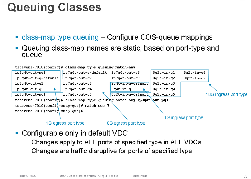
Queuing Service Policies
- Queuing service policies leverage port ASIC capabilities to map traffic to queues and schedule packet delivery
- Define queuing classes
- -Class maps that define the COS-to-queue mapping
- - i.e., which COS values go in which queues?
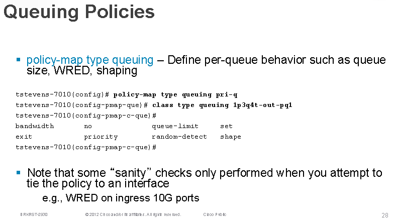
- Define queuing policies
- - Policy maps that define how each class is treated
- - i.e., how does the queue belonging to each class behave?
- Apply queuing service policies
- - Service policies that apply the queuing policies
- - i.e., which policy is attached to which interface in which direction?
Queue Attributes
- priority — defines queue as the priority queue
- bandwidth — defines WRR weights for each queue
- shape — defines SRR weights for each queue
- - Note: enabling shaping disables PQ support for that port
- queue-limit — defines queue size and defines tail-drop thresholds
- random-detect — sets WRED thresholds for each queue
- - Note: WRED and tail-drop parameters are mutually exclusive on a per-queue basis
The Nexus 7K will match on the standard values such as CoS, IPP, DSCP, packet length, and protocol.
The supported protocols are:
|
Argument |
Description |
|
arp |
Address Resolution Protocol (ARP) |
|
bridging |
Bridging |
|
cdp |
Cisco Discovery Protocol (CDP) |
|
clns |
Connectionless Network Service (CLNS) |
|
clns_es |
CLNS End Systems |
|
clns_is |
CLNS Intermediate System |
|
dhcp |
Dynamic Host Configuration (DHCP) |
|
isis |
Intermediate system to intermediate system (IS-IS) |
|
ldp |
Label Distribution Protocol (LDP) |
|
netbios |
NetBIOS Extended User Interface (NetBEUI) |
The support DSCP values are:
|
Value |
DSCP Value |
|
af11 |
AF11 dscp (001010)—decimal value 10 |
|
af12 |
AF12 dscp (001100)—decimal value 12 |
|
af12 |
AF13 dscp (001110)—decimal value 14 |
|
af21 |
AF21 dscp (010010)—decimal value 18 |
|
af22 |
AF22 dscp (010100)—decimal value 20 |
|
af23 |
AF23 dscp (010110)—decimal value 22 |
|
af31 |
AF31 dscp (011010)—decimal value 26 |
|
af31 |
AF40 dscp (011100)—decimal value 28 |
|
af33 |
AF33 dscp (011110)—decimal value 30 |
|
af41 |
AF41 dscp (100010)—decimal value 34 |
|
af42 |
AF42 dscp (100100)—decimal value 36 |
|
af43 |
AF43 dscp (100110)—decimal value 38 |
|
cs1 |
CS1 (precedence 1) dscp (001000)—decimal value 8 |
|
cs2 |
CS2 (precedence 2) dscp (010000)—decimal value 16 |
|
cs3 |
CS3 (precedence 3) dscp (011000)—decimal value 24 |
|
cs4 |
CS4 (precedence 4) dscp (100000)—decimal value 32 |
|
cs5 |
CS5 (precedence 5) dscp (101000)—decimal value 40 |
|
cs6 |
CS6 (precedence 6) dscp (110000)—decimal value 48 |
|
cs7 |
CS7 (precedence 7) dscp (111000)—decimal value 56 |
|
default |
Default dscp (000000)—decimal value 0 |
|
ef |
EF dscp (101110)—decimal value 46 |
The supported precedence values are:
|
Value |
Precedence Value |
|
0-7 |
IP precedence value |
|
critical |
Critical precedence (5) |
|
flash |
Flash precedence (3) |
|
flash-override |
Flash override precedence (4) |
|
immediate |
Immediate precedence (2) |
|
internet |
Internetwork control precedence (6) |
|
network |
Network control precedence (7) |
|
priority |
Priority precedence (1) |
|
routine |
Routine precedence (0) |
The Nexus 7K also supports QoS groups: locally significant QoS values that can be manipulated and matched within the system. The range is from 0 to 126.
The Nexus 7K also supports discard classes: locally significant values that can be matched and manipulated within the system. The range is from 0 to 63.
Note: If you match on an ACL, no other match criteria, except the packet length, can be specified in a match-all class. In a match-any class, you can match on ACLs and any other match criteria.
Classification has the following configuration guidelines and limitations:
- You can specify a maximum of 1024 match criteria in a class map.
- You can configure a maximum of 4096 classes for use in a single policy map.
- When you match on an ACL, the only other match you can specify is the Layer 3 packet length in a match-all class.
- The match-all option in the class-map type qos match-all command is not supported. The match criteria of this command becomes the same as in the class-map type qos match-any command. The class-map type qos match-all command yields the same results as the class-map type qos match-any command.
- You can classify traffic on Layer 2 ports based on either the port policy or VLAN policy of the incoming packet but not both. Either the port policy or the VLAN policy takes effect but not both. If both are present, the device acts on the port policy and ignores the VLAN policy.
- The match cos command is not supported in the egress direction.
- If a QoS policy is configured with one type of match criteria, a different type of match criteria cannot be used.
- When you display the queuing statistics, the statistics for cbqosmib is shown per action, not per class level.
- Queuing cbqosmib will only be pulled when the following actions are configured: queue-limit, random-detect, bandwidth, and priority.
- For F1 module proxy-forwarded traffic, ACL classification is matched against the layer 3 protocol number (protocols other than ICMP, IGMP, IPv4, TCP or UDP are matches as IPv4)
- show policy-map interface [interface type] type queuing uses L2 MTU (Frame length) and counts as a full packet length.
- show policy-map interface [interface type] type qos uses L3 MTU (Packet length)
Note: Tunneled IP packets are matched unless the tunneling protocol is also IP, and the match applies to the outer IP header and not the encapsulated IP header.
|
Marking Feature |
Description |
||
|
DSCP |
Layer 3 DSCP.
|
||
|
IP precedence |
Layer 3 IP precedence.
|
||
|
CoS |
Layer 2 class of service (CoS). |
||
|
QoS group |
Locally significant QoS values that can be manipulated and matched within the system. The range is from 0 to 126. |
||
|
Discard class |
Locally significant values that can be matched and manipulated within the system. The range is from 0 to 63. If you manipulate this discard class value, you cannot manipulate dscp values and vice-versa. |
||
|
Ingress and egress ports |
Status of the marking applies to incoming or outgoing packets. |
||
|
Using table maps |
Method to use table maps for marking. |
Marking has the following configuration guidelines and limitations:
- The set cos command can only be used in ingress policies when no other set commands are used for the same packet for egress.
- The set qos-group command can only be used in ingress policies.
- The set discard-class command can only be used in ingress policies.
- When PIM is enabled on the switch virtual interface (SVI), you cannot mark the Layer 2 switched multicast traffic on that VLAN.
- Egress QoS policies on Layer 2 ports are not supported on VDCs of any module type.
- A VLAN configuration with an egress QoS policy is not supported on VDCs that consist of F1 modules or any module plus an F1 module. However, a VLAN configuration with an egress QoS policy is supported on VDCs of the following module types:
- M1 and/or M2 plus an F2e
- M1
- M2 and F3
- M3 and F3
- F2 and/or F2e
- F3
- Egress policies on VLAN configurations do not support set match on CoS.
- Egress policies on VLAN configurations do not support set QoS group or discard class.
- Proxy-routed marking from F1 and/or F2e modules to M modules is not supported on the Layer 2 ingress port. However, marking that is applied under the VLAN is supported on the Layer 2 ingress port.
- To achieve scalability with remarking QoS policy on large number of interfaces, disable the QoS statistics on policy level. Enter the no qos statistics command, which disables global statistics, or enter the service-policy type qos output DSCP no-stats command per policy. The scalability configuration will not exist if policers are used.
The default behaviour of the device is to preserve the DSCP value or to trust DSCP. To make the port untrusted, change the DSCP value. Unless you configure a QoS policy and attach that policy to specified interfaces, the DSCP value is preserved.
Note: The internal label QoS group is not supported through table maps.
Note: Marking down in the police command requires the use of a table map.
Note: By default, unmapped values (in the table maps) are copied to the destination value, so that the destination value is the same as the source value.
You can use mutation in policies that contain policing commands, but you cannot use mutation in queuing and scheduling commands.
- You use a hierarchical policy for mutation mapping. Hierarchical policies are not supported for any other use.
- The device supports only one level of hierarchy.
- You can configure up to 14 table maps for use in ingress interfaces and up to 15 table maps for use in egress interfaces.
- Before you delete a referenced policy map, you must first remove all references to that policy map.
- You can use only like parameters (for example, cos-cos) when you create a mutation map. Mutation maps with dissimilar types (for example, cos-dscp) are not supported.
Nexus 7K’s support single-rate, dual-rate, and color-aware policers. When the data rate exceeds the user-supplied values, packets are either marked down or dropped. Single-rate policers monitor the specified committed information rate (CIR) of traffic. Dual-rate policers monitor both CIR and peak information rate (PIR) of traffic. Color-aware policers assume that traffic has been previously marked with a color. This information is then used in the actions taken by this type of policer.
Shared Policers:
QoS applies the bandwidth limits specified in a shared policer cumulatively to all flows in the matched traffic. A shared policer applies the same policer to more than one interface simultaneously.
For example, if you configure a shared policer to allow 1 Mbps for all Trivial File Transfer Protocol (TFTP) traffic flows on VLAN 1 and VLAN 3, the device limits the TFTP traffic for all flows combined on VLAN 1 and VLAN 3 to 1 Mbps.
The shared policer is also referred to as the named aggregate policer in other Cisco documentation.
Configuring Color-Aware Policing:
Color-aware policing implies that the QoS DSCP field in a class of traffic has been previously marked with values that you can use in a policer. This feature allows you to mark traffic at one node in a network and then take action based on this marking at a subsequent node.
You can use one or more of the four police command class maps conform-color or exceed-color to perform color-aware policing. These keywords require a class-map name that is used to classify packets. Based on the match criteria that you specify in the class maps, the traffic is classified into one of these two classes or class-default if there is no match. The policer then takes the following action:
- Packets that belong to the conform-color class are policed with the cir and pir arguments to the police command.
- Packets that belong to the exceed-color class are policed only against the pir argument to the police command. If pir is not specified, the cir values are used.
- Packets that end up in class-default because they fail to match either the conform-color or exceed-color class will immediately take the violate action.
A color other than class-default cannot be assigned to the violate action because according to RFC 2697 and RFC 2698, all packets must be assigned a color.
Policing has the following configuration guidelines and limitations:
- F1 modules do not support policing.
- Each module polices independently, which might affect QoS features that are being applied to traffic that is distributed across more than one module. The following are examples of these QoS features:
- Policers applied to a port channel interface.
- Egress policers applied to a Layer 3 interface. The device performs egress policing decisions at the ingress module.
- Policers applied to a VLAN.
- All policers in either the ingress or egress direction must use the same mode. For example, if the color-aware mode is needed for a class, all classes in that policy in the same direction must be in the color-aware mode.
- The police rate for traffic between two different port ASIC instances on a module is set differently for M1 modules and F2 modules.
- When traffic is between two different instances on an M1 module, the police rate is shared between the instances. If you add another interface as a third instance, the same police rate is shared as was between the two existing instances. For example, if a police rate of 5 Mbps is shared between two instances and an interface on a third instance is added, then the police rate of 5 Mbps is shared among all three instances.
- When traffic is between two different instances on an F2 module, the police rate is not shared between the instances. The police rate is shared only among the interfaces on the same instance. For example, if a police rate of 5 Mbps is set for the interfaces on one instance, this 5 Mbps police rate is not shared with interfaces on another instance.
- In M3 modules, MQC supports a shared-policer construct, which allows traffic from multiple targets to share a common policer. The only restriction is that the policing rate for a shared-policer can be supported only within a single decision engine instance.
- When the policer uses a MAC ACL for traffic classification, the policer is applied differently by M1 modules and F2 modules. (The application depends on the mac packet-classify command.)
- On M1 modules, the policer is applied only when the mac packet-classify command is enabled.
- On F2 modules, the policer is applied regardless whether the mac packet-classify command is enabled or not.
|
Policer Types and Actions from Police Arguments Present |
||||
|
Police Arguments Present |
Policer Type |
Policer Action |
||
|
cir, but not pir, be, or violate |
1-rate, 2-color |
≤ cir, conform; else violate |
||
|
cir and pir |
1-rate, 3-color |
≤ cir, conform; ≤ pir, exceed; else violate
|
||
|
cir and pir |
2-rate, 3-color |
≤ cir, conform; ≤ pir, exceed; else violate |
||
Note: You must specify the identical value for pir and cir to configure 1-rate 3-color policing.
|
Policer Actions for Exceed or Violate |
|
|
Action |
Description |
|
drop |
Drops the packet. This action is available only when the packet exceeds or violates the parameters. |
|
set dscp dscp table (cir-markdown-map | pir-markdown-map) |
Sets the specified fields from a table map and transmits the packet. For more information on the system-defined or default table maps, see “Configuring Marking.” This action is available only when the packet exceeds the parameters (use the cir-markdown-map) or violates the parameters (use the pir-markdown-map). |
Policer Actions for Conform
|
Action |
Description |
|
transmit |
Transmits the packet. This action is available only when the packet conforms to the parameters. |
|
set-prec-transmit |
Sets the IP precedence field to a specified value and transmits the packet. This action is available only when the packet conforms to the parameters. |
|
set-dscp-transmit |
Sets the Differentiated Service Code Point (DSCP) field to a specified value and transmits the packet. This action is available only when the packet conforms to the parameters. |
|
set-cos-transmit |
Sets the class of service (CoS) field to a specified value and transmits the packet. This action is available only when the packet conforms to the parameters |
|
set-qos-transmit |
Sets the QoS group internal label to specified value and transmits the packet. This action can be used only in input policies and is available only when the packet conforms to the parameters. |
|
set-discard-class-transmit |
Sets the discard-class internal label to a specified value and transmits the packet. This action can be used only in ingress policies and is available only when the packet conforms to the parameters. |
Note: A policer can only drop or mark down packets that exceed or violate the specified parameters.
You can apply weighted random early detection (WRED) to a class of traffic, which allows packets to be dropped based on the CoS field. The WRED algorithm allows you to perform proactive queue management to avoid traffic congestion.
You can schedule traffic by imposing a maximum data rate on a class of traffic so that excess packets are retained in a queue to smooth (constrain) the output rate.
The following are the three types of policies:
- network qos—Defines the characteristics of QoS properties network wide.
- qos—Defines MQC objects that you can use for marking and policing.
- queuing—Defines MQC objects that you can use for queuing and scheduling as well as a limited set of the marking objects.
Note: You can apply only ingress traffic actions for type QoS policies on Layer 2 interfaces. You can apply both ingress and egress traffic actions for type QoS policies on Layer 3 interfaces
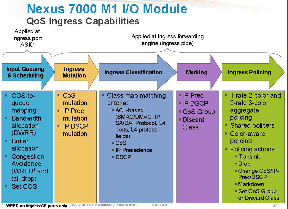
The sequence of QoS actions on ingress traffic is as follows:
1. Queuing and scheduling
2. Mutation
3. Classification
4. Marking
5. Policing
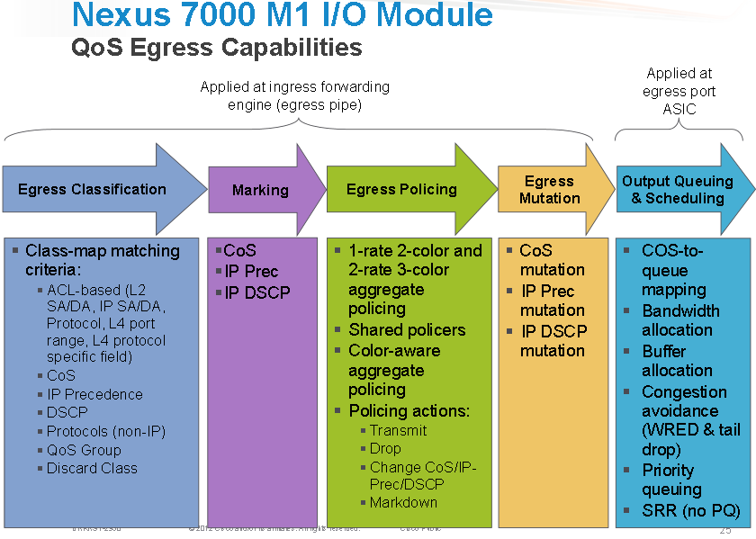
The sequencing of QoS actions on egress traffic is as follows:
1. Classification
2. Marking
3. Policing
4. Mutation
5. Queuing and scheduling
Note: Mutation occurs much closer to the beginning of the traffic actions on the ingress packets, and any further classification and policing is based on the changed QoS values.
The QoS queuing features are enabled by default. By default, the device always enables a system default queuing policy, or system-defined queuing policy map, on each port and port channel.
|
Trust DSCP/CoS by Default |
Ingress |
Egress (After Traffic is Routed) |
|
SVI |
CoS |
DSCP |
|
Routed Interface |
DSCP |
DSCP |
|
Layer 2 Interface |
CoS |
DSCP |
When the Layer 2 Interface is an access port, it is considered as no CoS. CoS is set to 0 in the case when access to the trunk interface with bridged traffic, even if DSCP bits are set.
Note: When traffic is routed, the DSCP value is used (by default) to derive the egress queue. If the egress interface is the trunk, the CoS is derived from the DSCP value of the routed packet.
|
System Defined Queuing Policy Maps |
|
|
Queuing Policy Map Name |
Description |
|
default-in-policy |
Input queuing policy map that is attached to all module ports to which you do not apply a queuing policy map. The default configuration values are as follows: policy-map type queuing default-in-policy class type queuing in-q1 queue-limit percent 50 bandwidth percent 80 class type queuing in-q-default queue-limit percent 50 bandwidth percent 20 |
|
default-out-policy |
Output queuing policy map that is attached to all module ports to which you do not apply a queuing policy map. The default configuration values are as follows: policy-map type queuing default-out-policy class type queuing out-pq1 priority level 1 queue-limit percent 16 class type queuing out-q2 queue-limit percent 1 class type queuing out-q3 queue-limit percent 1 class type queuing out-q-default queue-limit percent 82 bandwidth remaining percent 25 |
System-Defined Type queuing Class Maps:
|
Class Map Queue Name |
Description |
Default CoS Values |
|
1 Gigabit Module Ingress: 2 queues with 4 thresholds per queue |
||
|
2q4t-in-q1 |
Ingress queue 1 of 2q4t type |
5-7 |
|
2q4t-in-q-default |
Ingress default queue of 2q4t type |
0-4 |
|
1 Gigabit Module Egress: 1 strict priority queue and 3 normal queues with 4 thresholds per queue |
||
|
1p3q4t-out-pq1 1 |
Egress priority queue of 1p3q4t type |
5-7 |
|
1p3q4t-out-q2 |
Egress queue 2 of 1p3q4t type |
— |
|
1p3q4t-out-q3 |
Egress queue 3 of 1p3q4t type |
— |
|
1p3q4t-out-q-default |
Egress default queue of 1p3q4t type |
0-4 |
|
10 Gigabit Module Ingress: 8 queues with 2 thresholds per queue |
||
|
8q2t-in-q1 |
Ingress queue 1 of 8q2t type |
5-7 |
|
8q2t-in-q2 |
Ingress queue 2 of 8q2t type |
— |
|
8q2t-in-q3 |
Ingress queue 3 of 8q2t type |
— |
|
8q2t-in-q4 |
Ingress queue 4 of 8q2t type |
— |
|
8q2t-in-q5 |
Ingress queue 5 of 8q2t type |
— |
|
8q2t-in-q6 |
Ingress queue 6 of 8q2t type |
— |
|
8q2t-in-q7 |
Ingress queue 7 of 8q2t type |
— |
|
8q2t-in-q-default |
Ingress default queue of 8q2t type |
0-4 |
|
10 Gigabit Module Egress: 1 strict priority queue and 7 normal queues with 4 thresholds per queue |
||
|
1p7q4t-out-pq1 1 |
Egress priority queue of 1p7q4t type |
5-7 |
|
1p7q4t-out-q2 |
Egress queue 2 of 1p7q4t type |
— |
|
1p7q4t-out-q3 |
Egress queue 3 of 1p7q4t type |
— |
|
1p7q4t-out-q4 |
Egress queue 4 of 1p7q4t type |
— |
|
1p7q4t-out-q5 |
Egress queue 5 of 1p7q4t type |
— |
|
1p7q4t-out-q6 |
Egress queue 6 of 1p7q4t type |
— |
|
1p7q4t-out-q7 |
Egress queue 7 of 1p7q4t type |
— |
|
1p7q4t-out-q-default |
Egress default queue of 1p7q4t type |
0-4 |
1These are either priority or normal queues. If you use the priority keyword in your configuration, these queues are used as priority queues. Otherwise, they are used as normal queues.
F Series I/O Module Specifics:
F Series Queuing:
On an F-Series module, a queuing policy is closely coupled with the network qos policy. For each network qos policy that is activated, its corresponding default queuing policy is automatically selected for the system target. In the ingress direction, either two or four queues (buffer pools) are formed depending on the policy template. In the egress direction, there are four physical queues for qos policy templates on Cisco Nexus 7000 Series devices, except on the Cisco Nexus 7710 switch and Cisco Nexus 7718 switch, where, beginning with Cisco Release 6.2(2), there is support for eight physical queues.
The system queuing policy applied by default can be overridden on a per-port basis. In general, the user-configured queuing policies are per virtual device context (VDC).
Ingress queuing determines the following attributes:
- Queue-limit—Amount of buffers to be allocated for a class of service (CoS).
- Bandwidth—Priority grouping and its bandwidth allocation advertised using the Data Center Bridging Capability Exchange Protocol (DCBXP).
- Set CoS—Untrusted port default CoS (similar to the M1 modules).
Egress queuing determines the following attributes:
- Bandwidth—Differential Weighted Round Robin (DWRR) bandwidth for a given queue and the group.
- Priority level—The priority level of the queue.
- Shape—The shaper for the queue.
F Series Ingress Queuing:
You use the ingress queuing to partition the port ingress buffers that are 1.25 MB and an additional 256 KB (a total of 1.5 MB) to absorb the frames in transit after pause has been sent. This buffer is partitioned among the eight CoS values. The number of partitions is fixed for a given network qos template. The incoming CoS values are mapped to each partition. Each buffer partition is considered as an ingress queue.
There is a high threshold and a low threshold at which the pause or resume frames are generated when a threshold is met. This requirement is applicable to the no-drop CoS only. The frames that are in transit are absorbed by a skid buffer after a pause is generated. If the number of frames exceed the skid buffer threshold, the frames are tail dropped. There are three thresholds for drop eligible (DE), non-DE, and Bridge Protocol Data Unit (BPDU) frames for dropping. For the drop CoS, the high and low thresholds are the same.
The default policy ingress queues are created as follows:
- Different queues per drop class:
- Drop queue =70% buffers; no-drop queue = 30% buffers
- Different queues for priority and nonpriority CoS in a given drop class:
- Nonpriority queue= 90% buffers; priority queue = 10% buffers
Each network qos policy has a corresponding default ingress queuing policy (template) and is automatically activated for the system. They are the default-4q-8e-in-policy, default-4q-7e-in-policy, default-4q-6e-in-policy, default-4q-4e-in-policy, default-8e-4q8q-in-policy, default-7e-4q8q-in-policy, default-6e-4q8q-in-policy, default-4e-4q8q-in-policy, and default-8e-4q4q-in-policy.
The predefined class map names (queue names) for ingress queuing are described in the table below.
|
Ingress Policy Maps |
Ingress Class Map Names |
|
default-4q-8e-in-policy |
2q4t-8e-in-q1 and 2q4t-8e-in-q-default |
|
default-4q-7e-in-policy |
4q4t-7e-in-q1, 4q4t-7e-in-q-default, 4q4t-7e-in-q3, and 4q4t-7e-in-q4 |
|
default-4q-6e-in-policy |
4q4t-6e-in-q1, 4q4t-6e-in-q-default, 4q4t-6e-in-q3, and 4q4t-6e-in-q4 |
|
default-4q-4e-in-policy |
4q4t-4e-in-q1, 4q4t-4e-in-q-default, 4q4t-4e-in-q3, and 4q4t-4e-in-q4 |
|
default-8e-4q4q-in-policy |
4q1t-8e-4q4q-in-q1, 4q1t-8e-4q4q-in-q-default, 4q1t-8e-4q4q-in-q3, and 4q1t-8e-4q4q-in-q4 |
|
default-8e-4q8q-in-policy (on Cisco Nexus 7710 / 7718 switches only) |
8e-4q8q-in-q1, 8e-4q8q-in-q-default, 8e-4q8q-in-q3, and 8e-4q8q-in-q4 |
|
default-7e-4q8q-in-policy (Cisco Nexus 7710 / 7718 switches only)
|
c-7e-4q8q-drop-in, c-7e-4q8q-ndrop-in 7e-4q8q-in-q1, 7e-4q8q-in-q-default and 7e-4q8q-in-q3 7e-4q8q-in-q4 |
|
default-6e-4q8q-in-policy (Cisco Nexus 7710 / 7718 switches only)
|
c-6e-4q8q-drop-in and c-6e-4q8q-ndrop-in 6e-4q8q-in-q1 and 6e-4q8q-in-q-default 6e-4q8q-in-q3 and 6e-4q8q-in-q4 |
|
default-4e-4q8q-in-policy (Cisco Nexus 7710 / 7718 switches only)
|
c-4e-4q8q-drop-in and c-4e-4q8q-ndrop-in 4e-4q8q-in-q1 and 4e-4q8q-in-q-default 4e-4q8q-in-q3 and 4e-4q8q-in-q4 |
Note:When a port becomes part of a port channel, the port inherits the policy of the port channel. When the port is moved out of the port channel, the default system queuing policy gets activated on the port.
By default, the queuing policy maps the priority CoS values (CoS 5-7) and nonpriority CoS values (CoS 0-4) into different ingress queues (IVL). CoS to ingress queue mapping is configured from the default VDC and the configuration is applied system wide.
Starting with the Cisco NX-OS 6.1 release, DSCP to IVL is supported on F2 modules, in the ingress direction, using the match dscp command with the 2q4t-8e-in-q1 class map and the 2q4t-8e-in-q-default class map. Starting with the Cisco NX-OS 6.1(2) release, DSCP to IVL is supported on IPV6 using F2e modules.
Guidelines for the match dscp command are as follows:
- The match dscp command is applicable only to queues that have at least one CoS value associated with it. If all DSCP values are not mapped to a nondefault ingress queue, the default queue should have the CoS values associated with it.
- DSCP queuing is automatically disabled when the user removes all match dscp commands (using no match statements).
- If the match dscp command is used in the 2q4t-8e-in-q1 class map to set some DSCP values, all remaining DSCP values are automatically mapped to the default queue.
|
Bridged Traffic |
When DSCP to ingress queue is enabled, the ingress queue selection is based on the DSCP value. However, the egress queue selection is based on the CoS value of the packet. If a CoS value does not exist, then all packets are accepted as CoS 0. To override this behavior and use DSCP for egress queue selection, an ingress QoS policy has to be applied that matches the DSCP value and uses the set dscp value command to set the DSCP to the same value as the matched DSCP on the class map. When CoS to ingress queue is enabled, the ingress queue selection is based on the CoS value. The egress queue selection is based on the CoS value of the packet, including non-IP packets. If a CoS value does not exist, then all packets are accepted as CoS 0. |
|
Routed Traffic without Proxy Mode (native F-Series modules) |
For port type Layer 3-to-Layer L3/SVI— When the DSCP-to-ingress queue is enabled, the ingress queue selection is based on the DSCP. However, the egress queue selection is based on the DSCP value when the Ingress Port is a Layer 3 type. When CoS-to-ingress queue is enabled for subinterfaces, the ingress queue selection is based on the CoS. However, the egress queue selection is based on the DSCP value when the ingress port is a Layer 3 type(subinterface) because the packets are routed and the DSCP-to-egress queue takes place. For port type Layer 2 SVI-to-SVI Layer 2— The egress queue selection is based on the DSCP value and does not rely on whether DSCP-to-ingress queue is enabled in ingress or not. When the CoS-to-ingress queue is enabled, the ingress queue selection is based on the CoS. The egress queue selection is based on the CoS value, or 0 for no CoS value, because the forwarding decision uses the CoS value to drive the egress queue. To use the DSCP/CoS value for egress queue selection, apply the type QoS policy to mutate the DSCP values one-to-one or set the DSCP values to one-to-one. |
|
Routed Traffic with Proxy Mode (mixed F-Series and M-Series modules) |
When the DSCP-to-ingress queue is enabled, the ingress queue selection is based on the DSCP. However, the egress queue selection is based on the DSCP value because packets are proxy routed on the M-Series module and the DSCP-to-egress queue takes place. When CoS-to-ingress queue is enabled, the ingress queue selection is based on the CoS. However, the egress queue selection is based on the DSCP value because packets are proxy routed on the M-Series module and the DSCP-to-egress queue takes place. |
Note: Modifying the default queuing policy maps is a disruptive operation that might cause frame drops.
F Series Egress Queueing:
You use egress queuing to determine how to schedule the traffic from the egress queues out of a port. The class map names represent queues and match cos represents the CoS values mapped to them
Note: CoS remapping is supported only in strict F-Series VDCs. It is not supported in F-Series/M1 mixed VDCs.
Each egress port has about 0.7 MB of buffers that are distributed equally among the 8 CoS values. A CoS has approximately 0.1 MB of buffers.
The default policy egress queues are created as follows:
- The drop and no-drop CoS must be mapped to different queues.
- The priority CoS is mapped to a strict priority (SP) queue. All the nonpriority CoS values are mapped to a DWRR queue.
- For all the non-8e templates, second level scheduling is used.
Note: Egress queues have a fixed size and are not user configurable.
Note: The egress port has four queues, except for the Cisco Nexus 7710 switch and the Cisco Nexus 7718 switch, whereby, beginning with Cisco Release 6.2(2), has support for eight queues (4q8q mode).
Each network qos policy has a corresponding default egress queuing policy (template) and is automatically activated for the system. They are the default-4q-8e-out-policy, default-4q-7e-out-policy, default-4q-6e-out-policy, default-4q-4e-out-policy, default-8e-4q8q-out-policy, default-7e-4q8q-out-policy, default-6e-4q8q-out-policy, default-4e-4q8q-out-policy and the default-8e-4q4q-out-policy. The flexible egress queues configuration is based on these queue types— 1p7qlt-8e, 1p7qlt-7e, 1p3q1t-8e, 1p3q1t-7e, 2p2q1t-4e, 2p6q1t-4e, 3p1q1t-6e, and 3p5qlt-6e.
For the Cisco Nexus 7710 switch and the Cisco Nexus 7718 switch, a hierarchical scheduling pattern is followed on the 7e-4q8q, 6e-4q8q, and 4e-4q8q templates.
|
Predefined Class Maps for Egress Queuing |
|
|
Egress Policy Names |
Egress Class Map Names |
|
default-4q-8e-out-policy |
1p3q1t-8e-out-pq1, 1p3q1t-8e-out-q2, 1p3q1t-8e-out-q3, and 1p3q1t-8e-out-q-default |
|
default-4q-7e-out-policy |
1p3q1t-7e-out-pq1, 1p3q1t-7e-out-q2, 1p3q1t-7e-out-q3, and 1p3q1t-7e-out-q-default |
|
default-4q-6e-out-policy |
3p1q1t-6e-out-pq1, 3p1q1t-6e-out-pq2, 3p1q1t-6e-out-pq3, and 3p1q1t-6e-out-q-default |
|
default-4q-4e-out-policy |
2p2q1t-4e-out-pq1, 2p2q1t-4e-out-pq2, 2p2q1t-4e-out-q3, and 2p2q1t-4e-out-q-default |
|
default-8e-4q4q-out-policy |
1p3q1t-8e-4q4q-out-pq1, 1p3q1t-8e-4q4q-out-q2, 1p3q1t-8e-4q4q-out-q3, and 1p3q1t-8e-4q4q-out-q-default |
|
default-8e-4q8q-out-policy (Cisco Nexus 7710 / 7718 switches only) |
8e-4q8q-out-q1(priority queue), 8e-4q8q-out-q2, 8e-4q8q-out-q3, 8e-4q8q-out-q4, 8e-4q8q-out-q5, 8e-4q8q-out-q6, 8e-4q8q-out-q7, and 8e-4q8q-out-q-default |
|
default-7e-4q8q-out-policy (Cisco Nexus 7710 / 7718 switches only)
|
c-7e-4q8q-drop-out and c-7e-4q8q-ndrop-out 7e-4q8q-out-q1 (priority queue), 7e-4q8q-out-q2, 7e-4q8q-out-q3, 7e-4q8q-out-q4, 7e-4q8q-out-q6, 7e-4q8q-out-q7, and 7e-4q8q-out-q-default 7e-4q8q-out-q5 |
|
default-6e-4q8q-out-policy (Cisco Nexus 7710 / 7718 switches only)
|
c-6e-4q8q-drop-out and c-6e-4q8q-ndrop-out 6e-4q8q-out-q1 (priority queue), 6e-4q8q-out-q2, 6e-4q8q-out-q3, 6e-4q8q-out-q6, 6e-4q8q-out-q7, and 6e-4q8q-out-q-default 6e-4q8q-out-q4 (priority queue) and 6e-4q8q-out-q5 (priority queue) |
|
default-4e-4q8q-out-policy (Cisco Nexus 7710 / 7718 switches only)
|
c-4e-4q8q-drop-out and c-4e-4q8q-ndrop-out 4e-4q8q-out-q1 (priority queue), 4e-4q8q-out-q2, 4e-4q8q-out-q3, and 4e-4q8q-out-q-default 4e-4q8q-out-q4 (priority queue), 4e-4q8q-out-q5, and 4e-4q8q-out-q6, 4e-4q8q-out-q7 |
You can modify an egress CoS to queue map irrespective of the ingress CoS to queue map by using the match cos command to configure the desired CoS to queue mapping.
An egress queue follows a hierarchical scheduling pattern when both drop classes are present. For a given network qos template, the egress queuing configuration (the number of DWRR queues, number of priority queues, and the scheduling hierarchy) are fixed. You can modify the bandwidth percentage, priority level, and shaper for a given port.
You use the bandwidth command to control the bandwidth allocated to an egress queue (traffic class).
Note: Bandwidth and priority are mutually exclusive on a class map (queue).
F Series Guidlines and Limitations:
Queuing and scheduling of F-Series modules have the following configuration guidelines and limitations:
- A queuing policy that is being activated should be consistent with the system network qos policy.
- The default queuing policy is attached to the system target (includes all F Series module ports), which is unlike the M1 series configuration where the default-in-policy is attached exclusively to each port.
- A queuing policy that is attached to a given port, overrides the system queuing policy on that port.
- The DSCP to egress queue selection for DSCP values 2-7 are set to be the same as the values for CoS 2-7. To change this setting, access the type QoS policy and use the set cos command to change the selected egress queue (applicable for all types of interfaces, such as access, trunk, routed, and so on).
- Egress policies on VLAN configurations do not support set match on CoS.
- Egress policies on VLAN configurations do not support set QoS group or discard class.
- The ingress type QoS policy supports set dscp/cos and set qos-group commands. You can configure either set dscp/cos or set qos-group command but not both. It is possible to migrate between these configurations at any time.
- F-Series modules do not support the following commands in a QoS policy:
- set discard-class or match discard-class
- set qos-group or match qos-group
- F Series modules do not support WRED in ingress queuing policies.
- F2 modules do not support CoS-to-queue mapping changes when M1 modules are also installed in the switch.
- F Series modules and M2 modules support shaping in the priority queue. M1 modules do not support shaping in the priority queue.
- F-Series modules and M2 modules support shaping in the priority queue. M1 modules do not support shaping in the priority queue.
- See the following information about the default-nq-8e-4q4q-policy template that support four ingress buffers:
- The default-nq-8e-4q4q-policy template is supported only with F2 modules.
- When F1 modules are online, the default-nq-8e-4q4q-policy template cannot be attached to the system qos.
- When the default-nq-8e-4q4q-policy template is attached to system qos, F1 modules are allowed to come online. However, all interfaces of the F1 modules go to the unallocated pool of the corresponding VDC.
- To make software downgrades nondisruptive, the following is required before the software downgrade:
- All user defined and cloned 8e-4q4q template queuing policies should be detached manually from all interfaces in each VDC.
- The default-nq-8e-4q4q-policy or the user defined/cloned 8e-4q4q template network-qos policy should be detached from the system qos.
- All user defined and cloned 8e-4q4q template network-qos policies should be removed manually from the default VDC.
- All user defined 8e-4q4q template queuing policies should be removed manually from all VDCs.
- Use the clear qos policies 8e-4q4q command in the default VDC to clear the default 8e-4q4q template policies. This command clears PPF (Policy Propagation Facility) nodes of 8e-4q4q template policies.
- After executing clear qos policies 8e-4q4q command, you must perform an in-service software downgrade (ISSD). If an ISSD is not performed, unexpected results might occur.
- The clear qos policies 8e-4q4q command is only supported in the default VDC. Using this command in the default VDC also clears the 8e-4q4q policy-maps in non-default VDCs.
- Reloading an F2 module brings up all the cleared default 8e-4q4q template related policy-maps by using the clear qos policies 8e-4q4q command.
- The default 8e-4q4q-policy template is published when a software upgrade is completed.
- See the following information about the Cisco 7710/7718 switches and the four default 4p8q policy templates that support eight egress queues on these switches:
- The default 4q8q-policy templates are supported and enabled by default on the Cisco Nexus 7710 switch and Cisco Nexus 7718 switch only.
- The default 4q8q-policy templates are supported on F2e modules only.
- DSCP queuing is enabled by default on the Cisco Nexus 7710/7718 switches. You must use the no hardware qos dscp-to-queue command to disable DSCP queuing on the switch. You can use the hardware qos dscp-to-queue command module type command to reenable DSCP queuing.
- See the following information about the match dscp command:
- Supports only the ingress queues for F2 modules for the 8E template. (It does not support egress queues, M1 queues, or fabric-qos queues.)
- Supports only ingress queues that have at least one CoS value associated with it without any restriction on which CoS value is used.
- Cannot be used in user-defined class maps.
- Cannot be used in a user configuration session.
- Must be disabled for ISSD. (If it is not disabled, the ISSD is disruptive).
- DSCP to IVL mapping is disabled by default.
- The queue-limit command cannot be specified based on CoS or DSCP values. The configured queue-limit sizes are applicable for both the DSCP and CoS values.
- No additional statistics are generated to differentiate how many packets are matched on DSCP or CoS.
- When DSCP to IVL is enabled, an interface uses the DSCP value as trusted for IP packets and the CoS value is trusted for non-IP packets.
- DSCP to IVL mapping is enabled by default on the Cisco Nexus 7710/7718 switches. You must use the no hardware qos dscp-to-queue command to disable DSCP to IVL mapping.
- DSCP to IVL mapping for FabricPath interfaces is not supported.
- DSCP to IVL mapping for IPv6 packets is not supported.
- DSCP to IVL mapping change is a disruptive operation and might cause BFD/routing protocols to flap.
- Shared buffer queuing between ports in a port group is available only on the F3 Series modules.
- Shared buffering is supported only in 8e and 8e-4q4q templates.
- Break-out ports do not support shared buffering.
- The M1, M2, F1, F2 and F2e modules do not support shared buffering.
- Ports in a port channel with a user-defined policy attached should have this same user-defined policy attached to the port groups.
- When a user-defined policy map is attached to a port group, the set cos and bandwidth commands are not applicable to the port group.
- Shared buffer queuing does not apply on the FEX Hif ports.
- When changing egress Class of Service (CoS) to queue mapping, ensure that you specify 2 or 3 seconds as the minimum time limit between changes. Otherwise, continuous traffic drop might occur.
- The M3 modules do not support per-queue counters for egress drops (multicast, unknown, unicast, or broadcasts). The egress drops will be per port and per Q-Default counter.
- Only 8e templates are supported on M3 modules.
- The M3 module supports only network-qos template with default-nq-8e-4q8q-policy. It does not support default-nq-4e-4q8q-policy, default-nq-6e-4q8q-policy, default-nq-7e-4q8q-policy, and default-nq-8021qav-4q8q-policy.
- The M3 module supports only the network-qos template. This template contains all the CoS values that match the MTU size.
- All data traffic will be enqueued to the default queue of dot1q-tunnel port because this port is untrusted by default.
Note: When you configure match all for a QoS class map by entering the class-map type qos match-all command, the match-all option does not work. Instead, the match criteria is always treated as match any.
Note: You configure QoS and queuing policies using the MQC class-map, policy-map, and table-map objects. A policy map contains either a QoS policy or queuing policy. You cannot use table maps in queuing policies.
You use type qos policies to mark, to apply mutations, to set the ingress port trust state, and to police packets.
You use type queuing policies to mark, shape, and queue packets. Marking is limited to the CoS field and does not support the use of table maps.
Note: The device restricts QoS policies to one per interface per direction (ingress or egress) for each of the policy types qos and queuing.
Policies that are defined at multiple interfaces have the following restrictions:
- A QoS policy attached to the physical port takes effect when the port is not a member of a port channel.
- A QoS policy attached to a port channel takes effect even when policies are attached to member ports.
- A QoS policy attached to a VLAN is applied to all ports in that VLAN that do not have other policies specifically applied.
- One ingress policy type queuing is supported for each Layer 2 port- and Layer 2 port-channel interface in both the ingress and egress direction. Egress type qos policies are not allowed on Layer 2 port or Layer 2 port-channel interfaces.
- One ingress and one egress QoS policy are supported for each Layer 3 and Layer 3 port-channel interface.
- One ingress and one egress QoS policy are supported for each VLAN.
- One ingress and one egress queuing policy are supported for each Layer 2 port-, Layer 2 port-channel, Layer 3 port-, and Layer 3 port-channel interface.
- When a VLAN or port channel, or both, touches multiple forwarding engines, all policies that enforce a rate are enforced per forwarding engine.
- For example, if you configure a policer on a specific VLAN that limits the rate for the VLAN to 100 Mbps and if you configure one switch port in the VLAN on one module and another switch port in the VLAN on another module, each forwarding engine can enforce the 100-Mbps rate. In this case, you could actually have up to 200 Mbps in the VLAN that you configured to limit the rate to 100 Mbps.
The interface where a QoS policy is applied is summarized in the table below. Each row represents the interface levels. The entry descriptions are as follows:
- Applied—Interface where an attached policy is applied.
- Present—Interface where a policy is attached but not applied.
- Not present—Interface where no policy is attached.
- Present or not—Interface where a policy is either attached or not, but not applied.
|
Port Policy |
Port-Channel Policy |
VLAN Policy |
|
Applied |
Not present |
Present or not |
|
Present or not |
Applied |
Present or not |
|
Not present |
Not present |
Applied |
Previous page: ME3600X/ME3800X Bandwidth, Policer & Shaper Oversubscription
Next page: Police traffic by IP