Date created: Tuesday, August 28, 2018 9:28:26 PM. Last modified: Wednesday, June 29, 2022 11:28:01 AM
OSPFv2 Inter-Area Filtering
In the topology below, the routes from each access area are not advertised into the backbone area 0 (area 1 see's no area 2 routes and vice verse). Equally from the backbone area only the loopback0 IP of the aggregation node within an access area is advertised (ACC1x nodes have AGG1-Lo0 and AGG2-Lo0 but not COR1-Lo0).
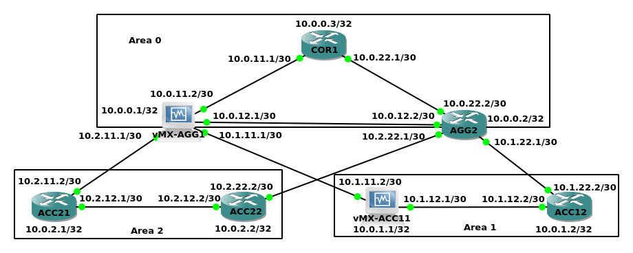
This is implemented so that each area can operate as a separate LDP domain, scaling independently of the others. This is in line with the Seamless MPLS architecture. The LSDB within OSPF is made from LSAs being flooded within an area, which causes each router to built a graph tree of the topology. After the graph tree is built then the prefixes that were attached to the LSAs are processed. This distinction is important, LSAs are processed first to build the graph then IP prefixes are processed to build the SPT afterwards, prefixes are extra information attached to LSAs.
Junos supports the commands "network-summary-export" and "network-summary-import". When using "set protocols ospf area <area> network-summary-export <policy>", prefixes are not exported out to that specific area but may be exported out to other areas. When using "network-summary-import" on the area where the prefix originates from stops it from being advertised to any area. The same policy can be used inbound to stop and non-area 0 prefixes from being imported into any other area. A policy for area 0 can match the local loopback0 IP to allow only that IP to be exported into the non-area 0 areas (so that LDP may build LSPs).
ACC11 Config:
set version 14.1R1.10
set system host-name ACC11
set interfaces ge-0/0/1 description ACC12-Fa0/1
set interfaces ge-0/0/1 unit 0 family inet address 10.1.12.1/30
set interfaces ge-0/0/1 unit 0 family mpls
set interfaces ge-0/0/2 description AGG1-ge-0/0/2
set interfaces ge-0/0/2 unit 0 family inet address 10.1.11.2/30
set interfaces ge-0/0/2 unit 0 family mpls
set interfaces lo0 unit 0 family inet address 10.0.1.1/32
set routing-options router-id 10.0.1.1
set protocols ospf area 0.0.0.1 interface lo0.0 passive
set protocols ospf area 0.0.0.1 interface ge-0/0/1.0 interface-type p2p
set protocols ospf area 0.0.0.1 interface ge-0/0/2.0 interface-type p2p
set protocols ldp interface ge-0/0/1.0
set protocols ldp interface ge-0/0/2.0
set protocols ldp interface lo0.0
AGG1 Config:
set version 14.1R1.10
set system host-name AGG1
set interfaces ge-0/0/2 description ACC11-ge-0/0/2
set interfaces ge-0/0/2 unit 0 family inet address 10.1.11.1/30
set interfaces ge-0/0/2 unit 0 family mpls
set interfaces ge-0/0/3 description AGG2-Fa0/1
set interfaces ge-0/0/3 unit 0 family inet address 10.0.12.1/30
set interfaces ge-0/0/3 unit 0 family mpls
set interfaces ge-0/0/4 description COR1-Fa0/0
set interfaces ge-0/0/4 unit 0 family inet address 10.0.11.2/30
set interfaces ge-0/0/4 unit 0 family mpls
set interfaces ge-0/0/5 description ACC21-Fa1/0
set interfaces ge-0/0/5 unit 0 family inet address 10.2.11.1/30
set interfaces ge-0/0/5 unit 0 family mpls
set interfaces lo0 unit 0 family inet address 10.0.0.1/32
set routing-options router-id 10.0.0.1
set protocols ospf area 0.0.0.0 network-summary-import ImportFromArea0
set protocols ospf area 0.0.0.0 interface lo0.0 passive
set protocols ospf area 0.0.0.0 interface ge-0/0/3.0 interface-type p2p
set protocols ospf area 0.0.0.0 interface ge-0/0/4.0 interface-type p2p
set protocols ospf area 0.0.0.1 network-summary-import ImportFromAreaN
set protocols ospf area 0.0.0.1 interface ge-0/0/2.0 interface-type p2p
set protocols ospf area 0.0.0.2 network-summary-import ImportFromAreaN
set protocols ospf area 0.0.0.2 interface ge-0/0/5.0 interface-type p2p
set protocols ldp interface ge-0/0/2.0
set protocols ldp interface ge-0/0/3.0
set protocols ldp interface ge-0/0/4.0
set protocols ldp interface ge-0/0/5.0
set protocols ldp interface lo0.0
set policy-options policy-statement ImportFromArea0 term 10 from route-filter 10.0.0.1/32 exact
set policy-options policy-statement ImportFromArea0 term 10 then accept
set policy-options policy-statement ImportFromArea0 term 20 then reject
set policy-options policy-statement ImportFromAreaN term 10 then reject
COR1 Config:
interface Loopback0
ip address 10.0.0.3 255.255.255.255
ip ospf 1 area 0
!
mpls ldp router-id lo0 force
!
interface FastEthernet0/0
description AGG1-E3
ip address 10.0.11.1 255.255.255.252
ip ospf network point-to-point
ip ospf prefix-suppression
ip ospf 1 area 0
duplex auto
speed auto
mpls ip
no shutdown
!
interface FastEthernet0/1
description AGG2-Fa1/1
ip address 10.0.22.1 255.255.255.252
ip ospf network point-to-point
ip ospf prefix-suppression
ip ospf 1 area 0
duplex auto
speed auto
mpls ip
no shutdown
!
router ospf 1
router-id 10.0.0.3
prefix-suppression
passive-interface default
no passive-interface FastEthernet0/0
no passive-interface FastEthernet0/1
no passive-interface Loopback0
exit
Below the output shows that the AGG1 router has only loopback IPs from area 0 as summary routes (Type 3 LSAs) in the other areas (1 & 2):
lab@AGG1> show ospf database

    OSPF database, Area 0.0.0.0
 Type       ID               Adv Rtr           Seq      Age  Opt  Cksum  Len
Router  *10.0.0.1         10.0.0.1         0x80000004   189  0x22 0xe27e  84
Router   10.0.0.2         10.0.0.2         0x80000005   102  0x22 0x2177  60
Router   10.0.0.3         10.0.0.3         0x80000005   185  0x22 0x9cfd  60

    OSPF database, Area 0.0.0.1
 Type       ID               Adv Rtr           Seq      Age  Opt  Cksum  Len
Router  *10.0.0.1         10.0.0.1         0x80000002  1060  0x22 0x5c78  48
Router   10.0.0.2         10.0.0.2         0x80000003   114  0x22 0xe9ff  36
Router   10.0.1.1         10.0.1.1         0x80000006   541  0x22 0x3822  84
Router   10.0.1.2         10.0.1.2         0x80000005   391  0x22 0xd4bf  60
Summary *10.0.0.1         10.0.0.1         0x80000002   437  0x22 0x9a8b  28
Summary  10.0.0.2         10.0.0.2         0x80000001   396  0x22 0x968d  28

    OSPF database, Area 0.0.0.2
 Type       ID               Adv Rtr           Seq      Age  Opt  Cksum  Len
Router  *10.0.0.1         10.0.0.1         0x80000002    51  0x22 0x854c  48
Router   10.0.0.2         10.0.0.2         0x80000003    50  0x22 0xfee8  36
Router   10.0.2.1         10.0.2.1         0x80000005    25  0x22 0x8815  60
Router   10.0.2.2         10.0.2.2         0x80000005    12  0x22 0xb0dd  60
Summary *10.0.0.1         10.0.0.1         0x80000002    11  0x22 0x9a8b  28
Summary  10.0.0.2         10.0.0.2         0x80000001   275  0x22 0x968d  28
The output below shows that the ACC11 router has only loopback routes for OSPF area 1 and the redistributed area 0 loopback routes from the two AGG1 and AGG2 ABR routers:
lab@ACC11> show ospf database

    OSPF database, Area 0.0.0.1
 Type       ID               Adv Rtr           Seq      Age  Opt  Cksum  Len
Router   10.0.0.1         10.0.0.1         0x80000003   327  0x22 0x5a79  48
Router   10.0.0.2         10.0.0.2         0x80000003   881  0x22 0xcbee  48
Router  *10.0.1.1         10.0.1.1         0x80000005    82  0x22 0x3a21  84
Router   10.0.1.2         10.0.1.2         0x80000004  1114  0x22 0xeb7a  72
Summary  10.0.0.1         10.0.0.1         0x80000003  1703  0x22 0x988c  28
Summary  10.0.0.2         10.0.0.2         0x80000001   515  0x22 0x968d  28
In the output above, the loopback IP from each ABR is redistributed from area 0 into area 1. Any router must originate a Type 1 LSA into any area in which they send LSAs. A Type 1 LSA is sent by each ABR which will contain all it's directly connected interfaces. For example, AGG1 will send 10.0.0.1/32 and 10.1.11.0/30. Now that the device has advertised a Type 1 LSA within the area, it can send a Type 3 Summary LSA to advertise it's loopback 0 IP address. This is not needed as the loopback 0 IP was in the Type 1 LSA. The point of Type 3 LSAs is to advertise inter-area prefixes which are not directly attached to the ABR.
This can be seen in the output below from ACC11 which shows the Type 1 LSA and Type 3 LSA received from AGG1:
lab@ACC11> show ospf database detail lsa-id 10.0.0.1

    OSPF database, Area 0.0.0.1
 Type       ID               Adv Rtr           Seq      Age  Opt  Cksum  Len
Router   10.0.0.1         10.0.0.1         0x80000002  1338  0x22 0x5c78  48
  bits 0x1, link count 2
  id 10.0.1.1, data 10.1.11.1, Type PointToPoint (1)
    Topology count: 0, Default metric: 1
  id 10.1.11.0, data 255.255.255.252, Type Stub (3)
    Topology count: 0, Default metric: 1
  Topology default (ID 0)
    Type: PointToPoint, Node ID: 10.0.1.1
      Metric: 1, Bidirectional
Summary  10.0.0.1         10.0.0.1         0x80000002   715  0x22 0x9a8b  28
  mask 255.255.255.255
  Topology default (ID 0) -> Metric: 0
The only way to make AGG1 (or AGG2) advertise it's loopback0 IP which is in area 0 into another area is to use a Type 3 LSA, and the only way to make AGG1 originate a Type 1 LSA containing its loopback0 IP into area 1 is by originating a Type 3 LSA 3. Both LSAs are required as the loopback0 IP on AGG1 is in area 0. If the inter-area policy on AGG1 is changed to block everything from area 0 then the Type 1 LSA is originated but no Type 3 LSA is originated. Because the prefix is in another area a Type 3 LSA is required to make it reachable within OSPF.
The output below shows that COR1 only has routes for OSPF area 0 and only has LDP labels for prefixes within this area so inter-area filtering is working as expected within area 0:
COR1#show ip ospf database

            OSPF Router with ID (10.0.0.3) (Process ID 1)

        Router Link States (Area 0)

Link ID         ADV Router      Age         Seq#       Checksum Link count
10.0.0.1        10.0.0.1        2851        0x80000004 0x00E27E 5
10.0.0.2        10.0.0.2        859         0x80000004 0x0076D0 5
10.0.0.3        10.0.0.3        818         0x80000004 0x00A0A9 5

COR1#show mpls forwarding-table
Local      Outgoing   Prefix           Bytes Label   Outgoing   Next Hop
Label      Label      or Tunnel Id     Switched      interface
17         Pop Label  10.0.0.2/32      0             Fa0/1      10.0.22.2
18         Pop Label  10.0.0.1/32      0             Fa0/0      10.0.11.2
19         No Label   10.0.12.0/30     0             Fa0/0      10.0.11.2
The results from an access layer PE such as ACC22 show the same results, that inter-area filtering is working as desired:
ACC22#show ip route
...
Gateway of last resort is not set

      10.0.0.0/8 is variably subnetted, 9 subnets, 2 masks
O IA     10.0.0.1/32 [110/2] via 10.2.12.1, 00:15:05, FastEthernet0/0
O IA     10.0.0.2/32 [110/2] via 10.2.22.1, 00:30:27, FastEthernet1/0
O        10.0.2.1/32 [110/2] via 10.2.12.1, 00:30:22, FastEthernet0/0
C        10.0.2.2/32 is directly connected, Loopback0
O        10.2.11.0/30 [110/3] via 10.2.12.1, 00:30:07, FastEthernet0/0
C        10.2.12.0/30 is directly connected, FastEthernet0/0
L        10.2.12.2/32 is directly connected, FastEthernet0/0
C        10.2.22.0/30 is directly connected, FastEthernet1/0
L        10.2.22.2/32 is directly connected, FastEthernet1/0

ACC22#show mpls forwarding-table
Local      Outgoing   Prefix           Bytes Label   Outgoing   Next Hop
Label      Label      or Tunnel Id     Switched      interface
18         Pop Label  10.0.0.2/32      0             Fa1/0      10.2.22.1
19         Pop Label  10.0.2.1/32      0             Fa0/0      10.2.12.1
20         Pop Label  10.2.11.0/30     0             Fa0/0      10.2.12.1
21         21         10.0.0.1/32      0             Fa0/0      10.2.12.1
The output below shows the AGG2 view of the IGP domain. We can see that it has all routes from all areas. It is worth noting that it has multiple copies of the AGG1 and AGG2 loopback0 within each area, as a Type 1 LSA and Type 3 LSA:
AGG2#show ip ospf  database

            OSPF Router with ID (10.0.0.2) (Process ID 1)

        Router Link States (Area 0)

Link ID         ADV Router      Age         Seq#       Checksum Link count
10.0.0.1        10.0.0.1        2987        0x80000004 0x00E27E 5
10.0.0.2        10.0.0.2        1004        0x80000004 0x0076D0 5
10.0.0.3        10.0.0.3        965         0x80000004 0x00A0A9 5

        Router Link States (Area 1)

Link ID         ADV Router      Age         Seq#       Checksum Link count
10.0.0.1        10.0.0.1        454         0x80000003 0x005A79 2
10.0.0.2        10.0.0.2        1004        0x80000003 0x00CBEE 2
10.0.1.1        10.0.1.1        209         0x80000005 0x003A21 5
10.0.1.2        10.0.1.2        1239        0x80000004 0x00EB7A 4

        Summary Net Link States (Area 1)

Link ID         ADV Router      Age         Seq#       Checksum
10.0.0.1        10.0.0.1        1830        0x80000003 0x00988C
10.0.0.2        10.0.0.2        638         0x80000001 0x00968D

        Router Link States (Area 2)

Link ID         ADV Router      Age         Seq#       Checksum Link count
10.0.0.1        10.0.0.1        152         0x80000003 0x00834D 2
10.0.0.2        10.0.0.2        1004        0x80000003 0x00F4C2 2
10.0.2.1        10.0.2.1        1118        0x80000004 0x005201 5
10.0.2.2        10.0.2.2        1128        0x80000004 0x00E652 5

        Summary Net Link States (Area 2)

Link ID         ADV Router      Age         Seq#       Checksum
10.0.0.1        10.0.0.1        1830        0x80000003 0x00988C
10.0.0.2        10.0.0.2        638         0x80000001 0x00968D
Juniper doesn't support prefix suppression for OSPF like Cisco does. In the output below it can be seen that ACC11 is receiving from ACC12 a Type 1 LSA which has a type 3 link to it's own loopback0 IP (10.0.1.2), a type 1 link to AGG2's loopback0 IP (10.0.0.2) and a type 3 link to ACC11's loopback0 IP (10.0.1.1).
lab@ACC11> show ospf database detail lsa-id 10.0.1.2

    OSPF database, Area 0.0.0.1
 Type       ID               Adv Rtr           Seq      Age  Opt  Cksum  Len
Router   10.0.1.2         10.0.1.2         0x80000005  1562  0x22 0xd4bf  60
  bits 0x0, link count 3
  id 10.0.1.2, data 255.255.255.255, Type Stub (3)
    Topology count: 0, Default metric: 1
  id 10.0.1.1, data 10.1.12.2, Type PointToPoint (1)
    Topology count: 0, Default metric: 1
  id 10.0.0.2, data 10.1.22.2, Type PointToPoint (1)
    Topology count: 0, Default metric: 1
  Topology default (ID 0)
    Type: PointToPoint, Node ID: 10.0.0.2
      Metric: 1, Bidirectional
    Type: PointToPoint, Node ID: 10.0.1.1
      Metric: 1, Bidirectional
ACC12 sends ACC11's own loopback0 IP back to him because OSPF reflects all routes it receives to all neighbours however, the cost in the output above is 1, it is 0 from ACC11 to reach it's own loopback interface so no received LSA will ever offer a lower cost path. 10.0.1.1 and 10.0.0.2 in the above output show as LSA Type 1 link type 1 networks, which is the Cisco prefix-suppression feature lying about the topology of the network to remove the need for the transit link prefix ranges.
Previous page: ISIS Basics
Next page: Layer 2 Edge Port Protection