Date created: Wednesday, January 23, 2013 10:06:16 PM. Last modified: Saturday, April 4, 2015 10:17:22 AM
Shift Register Hello World
Shift Register Hello World
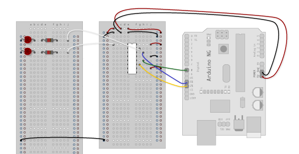
2 LEDs connected to a single 8 bit shift register. The red LED is connected to output 1 (or 0, the first output), and the yellow LED is connected to output 2 (or 1, the second output).
The red LED is activated when decimal 1 is translated into binary 00000001.
shiftOut(dataPin, clockPin, MSBFIRST, 1);
The yellow LED is turned on and the red LED off when decimal 2 is translated into binary 00000010.
shiftOut(dataPin, clockPin, MSBFIRST, 2);
Alternating between these two turns values the red LED on and yellow off, then the red off and yellow on, alternating between the two LEDs. To transtition between the two LEDs like the below video, there needs to be a period of time when both outputs are set to 1, with requires binary 00000011, which is decimal 3;
digitalWrite(latchPin, LOW);
shiftOut(dataPin, clockPin, MSBFIRST, 1);
digitalWrite(latchPin, HIGH);
delay(1000);
digitalWrite(latchPin, LOW);
shiftOut(dataPin, clockPin, MSBFIRST, 3);
digitalWrite(latchPin, HIGH);
delay(1000);
digitalWrite(latchPin, LOW);
shiftOut(dataPin, clockPin, MSBFIRST, 2);
digitalWrite(latchPin, HIGH);
delay(1000);
digitalWrite(latchPin, LOW);
shiftOut(dataPin, clockPin, MSBFIRST, 3);
digitalWrite(latchPin, HIGH);
delay(1000);
The same effect could be achieved with;
shiftOut(dataPin, clockPin, MSBFIRST, B00000001);
shiftOut(dataPin, clockPin, MSBFIRST, B00000011);
shiftOut(dataPin, clockPin, MSBFIRST, B00000010);
shiftOut(dataPin, clockPin, MSBFIRST, B00000011);
Previous page: Secret Agent Laser Challenge - Part 1
Next page: Mount AD Folders