Date created: Friday, December 8, 2017 10:17:03 AM. Last modified: Sunday, December 24, 2017 5:20:36 PM
ASR9000 Load-Balancing
References:
https://supportforums.cisco.com/t5/service-providers-documents/asr9000-xr-load-balancing-architecture-and-characteristics/ta-p/3124809
https://supportforums.cisco.com/t5/service-providers-documents/asr9000-xr-understanding-unequal-cost-multipath-ucmp-dmz-link/ta-p/3138853
BRKARC-2003 - 2017 Las Vegas
https://supportforums.cisco.com/t5/service-providers-documents/mpls-top-label-hash/ta-p/3156424
https://www.cisco.com/c/en/us/td/docs/routers/asr9000/software/asr9k_r5-3/addr-serv/configuration/guide/b-ipaddr-cg53asr9k/b-ipaddr-cg53asr9k_chapter_0100.html#con_1250252
https://tools.ietf.org/html/rfc6391
Contents:
Load-Balancing Overview
Hash Calculation for ECMP/LAG
Polarisation
Fragmentation
Sticky ECMP & Un-ECMP
Hash Fields
MPLS P Node Hashing Specifics
MPLS PE Node Hashing Specifics
Flow Aware Transport Pseudowires
Example ECMP/LAG Scenarios
Troubleshooting
Load-Balancing Overview
The ASR9000 series load-balancing scale limits are as follows:
L3 ECMP:
Non recursive or IGP paths: 32-way
Recursive or BGP paths:
8-way for Trident
32 way for Typhoon
64 way Typhoon in XR 5.1+
64 way Tomahawk XR 5.3+ (Tomahawk only supported in XR 5.3.0 onwards)
L2 Bundle:
64 members per bundle
The diagram below shows a flow diagram for next-hop resolution when multiple paths are available:
NRLDI = Non Recursive Load Distribution Index
RLDI = Recursive Load Distribution Index
ADJ = Adjacency (forwarding information)
LAG = Link Aggregation, e.g. EtherChannel or Bundle-Ether interface
OIF = Outgoing Interface, e.g. a physical interface like G0/0/0/0 or Te0/1/0/3
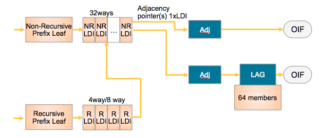
The diagram above shows that a Recursive BGP route could have 8 different next-hops, each of those 8 BGP next-hops could point to 32 potential IGP ways to get to that BGP next hop, and each of those 32 IGP paths can be a bundle which could consist of 64 members each.
The ingress linecard NPU performs the load-balancing calculation to decide the egress interface and thus linecard/NPU. This ensures that traffic is only sent to the line card NPU from where the traffic will egress. In the case of the hash calculation resulting in a next-hop adjacency that is reached through a LAG bundle, then another calculation is made to select a single lag member interface from the bundle. This means that adding or removing a LAG bundle member requires no update to the FIB because the hash calculation results in an adjacency pointer to an entire LAG bundle so bundle changes are "hidden" from the FIB and hashing processing.
The diagram below shows an example on Un-equal Cost Multipath Routing (BGP Next Hop 2 has many more adjacency entries that are all an equal cost to reach, compared to BGP Next Hop 1 which has just one adjacency, indicating multiple links towards BGP Next Hop 2, meaning more traffic should be sent to BGP Next Hop 2 assuming those multiple adjacencies/links towards BGP Next Hop 2 are higher bandwidth than the single link to BGP Next Hop 1):
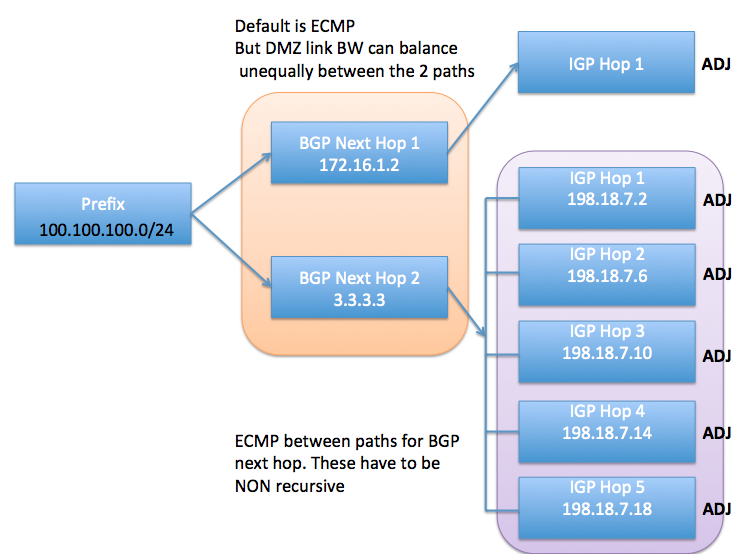
In this example the black "ADJ" text in bold represents IGP paths that are recursive. When using Un-ECMP the IGP next-hops must be non-resursive. In this example case those IGP next hops are static routes configured using the following configuraion:
router static
address-family ipv4 unicast
  3.3.3.3/32 198.18.7.2
  3.3.3.3/32 198.18.7.6
  3.3.3.3/32 198.18.7.10
  3.3.3.3/32 198.18.7.14
  3.3.3.3/32 198.18.7.18
Additional recursion is required to find the adjacency information and outgoing interface ID (lookup the outgoing interface and layer 2 rewrite details). In this example case when using static routes and Un-ECMP routing the egress interface must be specified in the static route configuration so that no further recursion is required:
router static
address-family ipv4 unicast
  3.3.3.3/32 GigabitEthernet0/0/0/5.10 198.18.7.2
  3.3.3.3/32 GigabitEthernet0/0/0/5.20 198.18.7.6
  3.3.3.3/32 GigabitEthernet0/0/0/5.30 198.18.7.10
  3.3.3.3/32 GigabitEthernet0/0/0/5.40 198.18.7.14
  3.3.3.3/32 GigabitEthernet0/0/0/5.50 198.18.7.18
Hash Calculation for ECMP/LAG
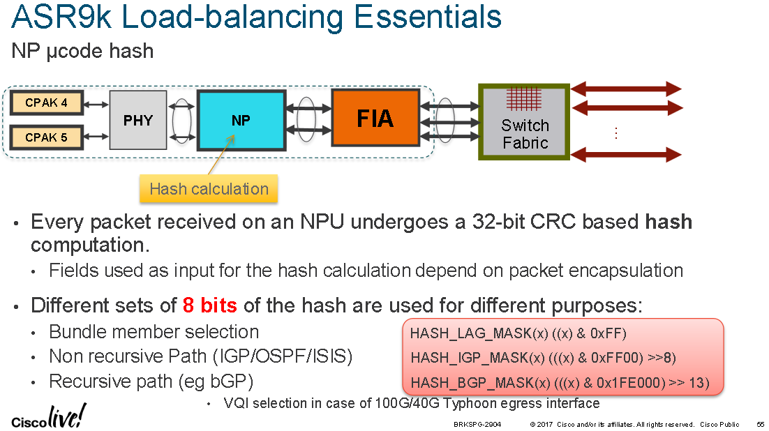
A hash is calculated from various header fields from a packet as it enters the ingress NPU. The header fields used for the hash calculation will vary depending on the protocols detected inside the packet. Once the protocol headers inside the packet have been identified and a hash has been computed, certain bits from the resulting hash value are then used as they hash key for the ECMP/LAG bucket selection.
Pre IOS-XR 4.0.x, Trident NPUs used a folded XOR methodology resulting in an 8 bit hash from which bits were selected.
Post IOS-XR 4.0.x, Trident NPUs use a checksum based calculation resulting in a 16 bit hash value.
Post IOS-XR 4.2.x, Trident NPUs use a checksum based calculation resulting in a 32 bit hash value.
Post IOS-XR 4.2.0, Typhoon NPUs use a CRC based calculation of the L3/L4 info and compute a 32 bit hash value.
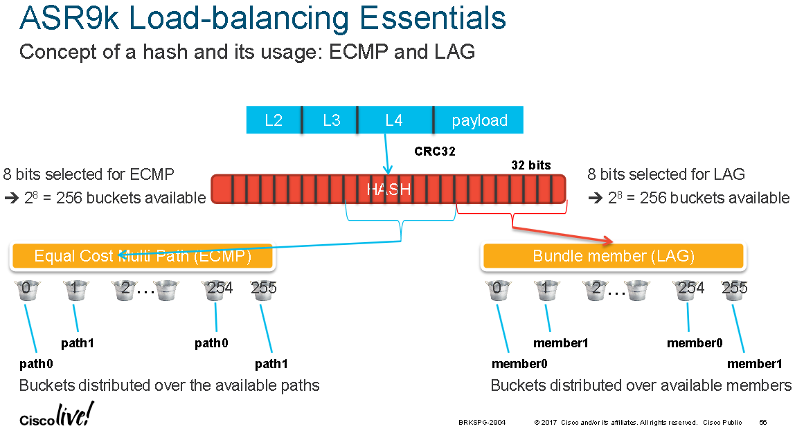
32-way non-recursive ECMP means that 5 bits of the hash result are being used. 8-way recursive ECMP means that 3 bits out of that hash result are used, 32-way recursive means 5 bits are being used and 64-way recursive means that 6 bits are being used. Equally 64 LAG members' means that 6 bits out of the hash result are being used.
The diagram below shows where in the physical pipeline the hash calculation takes place:
The diagram below shows that different bits from the hash result are used for ECMP or LAG selection:
By default CEF uses layer 4 fields for creating the ECMP hash key. This can set to layer 3 only or changed to include GTP as per the below (taken from IOS-XR 5.3.3-SP4):
RP/0/RSP0/CPU0:ASR9001(config)#cef load-balancing algorithm adjust ?
<0-31> Adjust count - configure up to 31 for Typhoon; up to 3 for Trident cards; Value will be masked on Trident (to make it <= 3) if this configured value is beyond 3
RP/0/RSP0/CPU0:ASR9001(config)#cef load-balancing fields ?
l3 Exclude L4 port info from hash calculation
l4 Load balancing at layer 4
RP/0/RSP0/CPU0:ASR9001(config)#cef load-balancing fields l3 ?
global configure globally system wide
RP/0/RSP0/CPU0:ASR9001(config)#cef load-balancing fields l3 global ?
<cr>
RP/0/RSP0/CPU0:ASR9001(config)#cef load-balancing fields l4 ?
gtp Includes GTP TEID for hash calculation
RP/0/RSP0/CPU0:ASR9001(config)#cef load-balancing fields l4 gtp ?
<cr>
Note bug CSCud10039 in which some 4.x versions of IOS-XR (below 4.3) weren't balancing traffic correctly on bundle-ethernet interfaces.
One can test the CEF load-balancing result by using the following command:
# Using Layer 3 and optionally layer 4 header info on IOS-XR 5.3.3-SP4:

RP/0/RSP0/CPU0:ASR9001#show cef exact-route 1.1.1.1 2.2.2.2 protocol tcp source-port 10 destination-port 20 ingress-interface te0/0/0/0

RP/0/RSP0/CPU0:ASR9001#show cef exact-route 1.1.1.1 2.2.2.2 protocol ?
    Enter protocol Number or name below
  AHP      authentication header
  EGP      exterior gateway protocol
  EIGP     EIGRP protocol
  ENCAP    Encapsulation header
  EON      IOS CNLP
  ESP      IPSEC Encapsulating Security Payload
  GRE      GRE encapsulation
  ICMP     control message protocol
  IDP      XNS IDP
  IGMP     group managment protocol
  IGRP     IGRP protocol
  IPINIP   IP in IP encapsulation
  L2TV3     L2TPv3 tunneling encapsulation
  NOSIP    KA9Q/NOS compatible IP over IP
  OSPF     OSPF protocols
  PCP      porotocol
  PUP      PUP protocol
  RAW      raw IP packet
  RSVP     resource reservation protocol
  SCTP     Stream Control Transmission
  TCP      TCP protocol
  TP       tp-4 with class negotiation
  UDP      UDP protocol
  UTI      UTI tunneling encapsulation


# IOS-XR 4.3.4-SP6

RP/0/RSP0/CPU0:ASR9001#show cef summary
Router ID is 10.0.0.8

IP CEF with switching (Table Version 0) for node0_RSP0_CPU0

  Load balancing: L4
…

#show cef misc
…
Platform capabilities:
--------------------------

L3 loadbalancing levels: 2
L3 Hash buckets: 32
L2 Hash buckets: 32
Forwarding stages: 2
Local label split: 3
Statistics support: No
Path per Tunnel class: 8
V4 update disabled: No
V6 update disabled: No
LBA tuples: 1
MRAPS support: No
Tunnel default class support: Yes
LISP ipv4/v4 decapsulation support: Yes
LISP ipv4/v6 decapsulation support: No
LISP unequal cost loadbalance support for ipv4 payload: No
LISP ipv6/v4 decapsulation support: Yes
LISP ipv6/v6 decapsulation support: No
LISP unequal cost loadbalance support for ipv6 payload: No


# IOS-XR 5.3.3-SP4

RP/0/RSP0/CPU0:ASR9001#show cef summary
Router ID is 0.0.0.0
IP CEF with switching (Table Version 0) for node0_RSP0_CPU0
  Load balancing: L4
…

#show cef misc
…
Platform capabilities:
--------------------------

L3 loadbalancing levels: 2
L3 Hash buckets: 64
L3 recursive Hash buckets: 32
L3 Unequal cost hash buckets: 0
Forwarding stages: 2
Local label split: 3
Statistics support: No
Path per Tunnel class: 8
V4 update disabled: No
V6 update disabled: No
LBA tuples: 1
MRAPS support: No
Tunnel default class support: Yes
Loadinfo choices are platform filtered
Prefix filter support: host prefix only
LISP ipv4/v4 decapsulation support: Yes
LISP ipv4/v6 decapsulation support: Yes
LISP unequal cost loadbalance support for ipv4 payload: No
Fallback support for ipv4: Yes
LISP ipv6/v4 decapsulation support: Yes
LISP ipv6/v6 decapsulation support: Yes
LISP unequal cost loadbalance support for ipv6 payload: No
Fallback support for ipv6: Yes
NHID (Next Hop ID) support: No
Backwalk (Dependents) required: No
Link MPLS IPv6 nexthop support: Yes
Exclude Deag backup paths: No
Polarisation
Polarisation can occur if there isn't enough entropy in the data being used to generate the hash key. This is more common with a layer 2 bundle link between P nodes for example, as the source and destination MAC address has little or no variance when compared with a layer 3 core bundle or when many ECMP paths exists. Another common source is elephant flows. It is also possible for the router IDs to have little variance and cause polarisation across multiple hops.
The command "cef load-balancing algorithm adjust <value>" introduced in IOS-XR 4.2.3 will left shift the bits used as the bucket index from the computed hash key. The Trident NPU allows for a shift maximum of 4 (performance reasons apparently). The Typhoon NPU allows for a shift of maximum of 32 bits. "The command allows for values larger than 4 on Trident, if you configure values large than 4 for Trident, you will effectively use a modulo, resulting in the fact that shift of 1 is the same as a shift of 5".
When bundle member links are not all of equal bandwidth (mixing 1G/10G/100G etc.) then IOS-XR will by default unevenly distribute the traffic so that a 100G link gets 10 times more traffic than a 10G link (in the background it assigns extra hash buckets to the same physical link).
Fragmentation
When fragmented packets are detected at ingress then layer 4 headers are no longer used as part of the hash key input. After the initial packet in a fragmented stream, subsequent packets don't have any layer 4 headers so they would produce a different hash result trying to use the same byte offsets within the packet headers. In the case of fragmented packets ASR9K's revert back to layer 3 headers only.
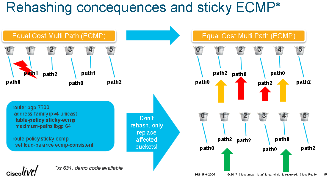
Sticky ECMP & Un-ECMP
The diagram below shows an RPL example which forces the ECMP hash result to be consistent even during a link/path failure. In this example there are three ECMP paths 0-2 and path 1 becomes unavailable. Normally the remaining two paths 0 and 2 would be rebalanced across all the available hash buckets, likely resulting in traffic destined to the unaffected paths being shifted between links and potentially out-of-order packets within the same flow. Using RPL the buckets for path 1 only are repointed to paths 0 and 2 and the buckets already pointed to paths 0 and 2 remain unchanged
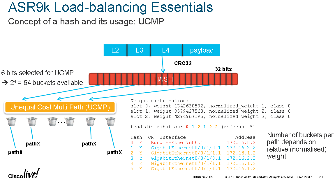
The diagram below shows that 6 bits are used for UCMP and the "show cef X.X.X.X/Y detail" command can be used to see the load-distribution amongst buckets:
Hash Fields
When hashing above layer 2; Typhoon and Tomahawk linecards can create hash keys using layer 3 and layer 4 headers, Trident linecards can only use layer 3 headers.
Pre IOS-XR 4.2.0 IPv6 hash calculation only used the last 64 bits of the IPv6 address, which were used to fold (XOR) and feed the hash function, this included the router ID and layer 4 headers. In IOS-XR 4.2.0 enhancements where made for the full IPv6 address to be taken into consideration with the layer 4 headers and router ID, just as with IPv4.
The following diagram shows which packet header fields are used for creating the hash value for ECMP/UCMP routing and LAG bundles:
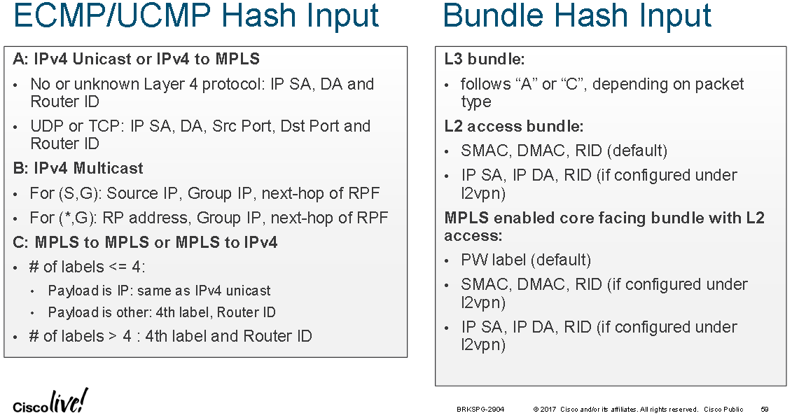
For ECMP/UCMP routing scenario A and C, IPv6 uses the same fields as with IPv4; IPv6 SA + IPv6 DA + Router ID if IP payload is not TCP or UDP, when it is TCP or UDP then the Src Port and Dst Port are included.
The command "sh arm router-ids" will show the Router ID which is typically the device's loopback0 IP address, to provide some local variance between devices.
For ingress bundle interfaces a bundle is considered layer 3 when the bundle interface has an IP address configured on it. For example this could be a layer 3 bundle between to P/PE routers. A bundle is considered layer 2 when it has the "l2transport" keyword configured on the bundle interface and it is used as an attachment circuit for a pseudowire or configured in a bridge domain or other l2vpn.
When using a layer 2 bundle interface as the core interface between two P/PE nodes the source and destination MAC addresses never change. Layer 3 hashing fields can be enabled for layer 2 bundle interfaces using the following configuration:
RP/0/RSP0/CPU0:ASR9001(config)#interface bundle-ether 1
RP/0/RSP0/CPU0:ASR9001(config-if)#bundle load-balancing hash ?
  dst-ip  Use the destination IP as the hash function
  src-ip  Use the source IP as the hash function
This applies to the ingress layer 2 bundle interface only under which the command is applied.
One can test the bundle-interface hash result using the following command:
RP/0/RSP0/CPU0:ASR9001#bundle-hash bundle-ether 1 location 0/0/CPU0
Calculate Bundle-Hash for L2 or L3 or sub-int based: 2/3/4 [3]:
Enter traffic type (1.IPv4-inbound, 2.MPLS-inbound, 3:IPv6-inbound, 4:IPv4-MGSCP, 5:IPv6-MGSCP): [1]: 2
Number of ingress MPLS labels is 4 or less: y/n [y]: y
Enter MPLS payload type (1.IPv4, 2:IPv6, 3:other): [1]: 1
Single SA/DA pair or range: S/R [S]:
Enter source IPv4 address [255.255.255.255]: 1.1.1.1
Enter destination IPv4 address [255.255.255.255]: 2.2.2.2
Compute destination address set for all members? [y/n]: y
Enter subnet prefix for destination address set: [32]: 24
Enter bundle IPv4 address [255.255.255.255]: 10.0.0.2
Enter L4 protocol ID. (Enter 0 to skip L4 data) [0]: 17
Enter layer 4 source port [0]: 10
Enter layer 4 destination port [0]: 20
Link hashed [hash_val:0] to is TenGigE0/0/2/0 ICL () LON 0 ifh 0x40001c0

 Destination address set for subnet 2.2.2.0:
  2.2.2.1 [hash:0] hashes to link TenGigE0/0/2/0 ICL ()

Another? [y]: n
More details about the bundle can be seen with the following command: "show bundle load-balancing bundle-ether 1 detail location 0/0/CPU0"
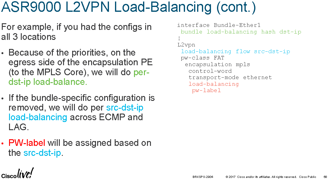
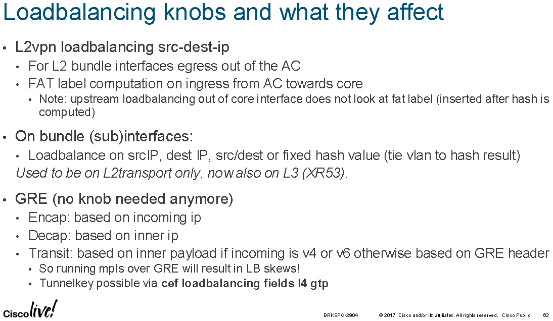
Similar configuration can be applied at the “l2vpn” device configuration level under which an ingress layer 2 bundle is joint to an ingress bridge domain or L2 MPLS VPN:
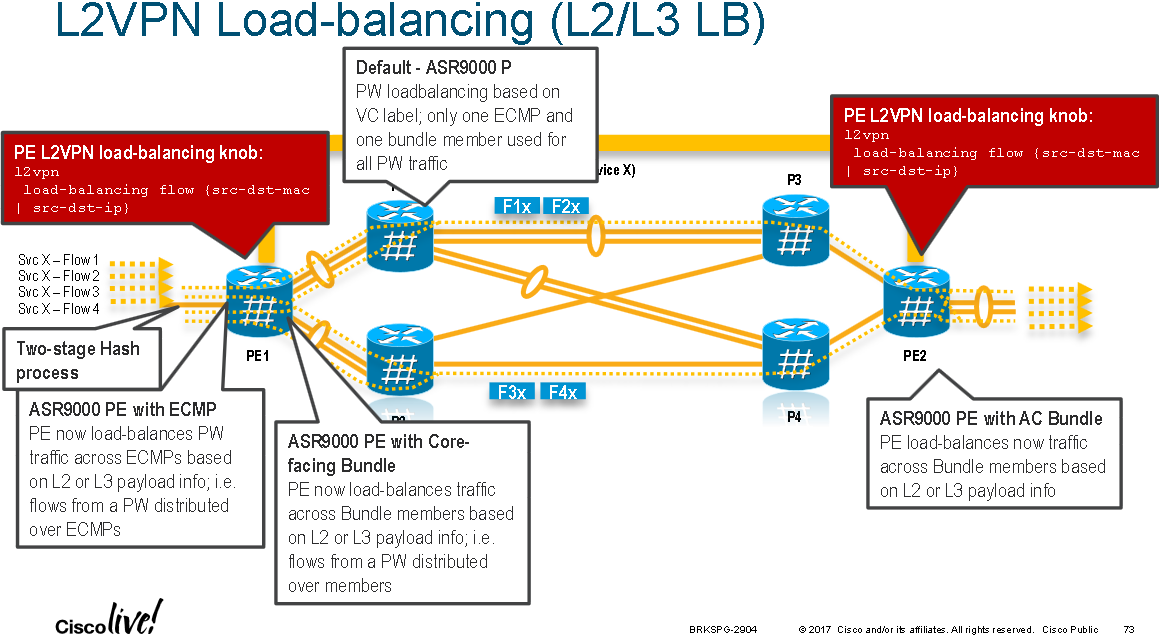
RP/0/RSP0/CPU0:ASR9001(config)#l2vpn
RP/0/RSP0/CPU0:ASR9001(config-l2vpn)#load-balancing flow ?
  src-dst-ip   Use source and destination IP addresses for hashing
  src-dst-mac  Use source and destination MAC addresses for hashing
Note: This used to be the "hw-module load-balance bundle l2-service l3-params" command which is now deprecated.
This L2VPN config above allows for an ingress layer 2 bundle between two P/PE nodes to hash based on IP level information which could be native IP over Ethernet or an IP L3VPN over MPLS. That is how a layer 3 bundle between P/PE nodes would behave. Otherwise a layer 2 bundle without the layer 3 hashing option configured (either at the bundle level or l2vpn level) will hash as per the above diagram, using MAC addresses and router ID (src-dst-mac is the default l2vpn configuration).
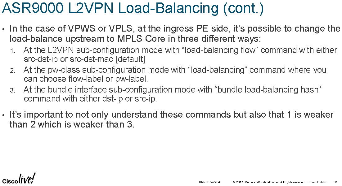
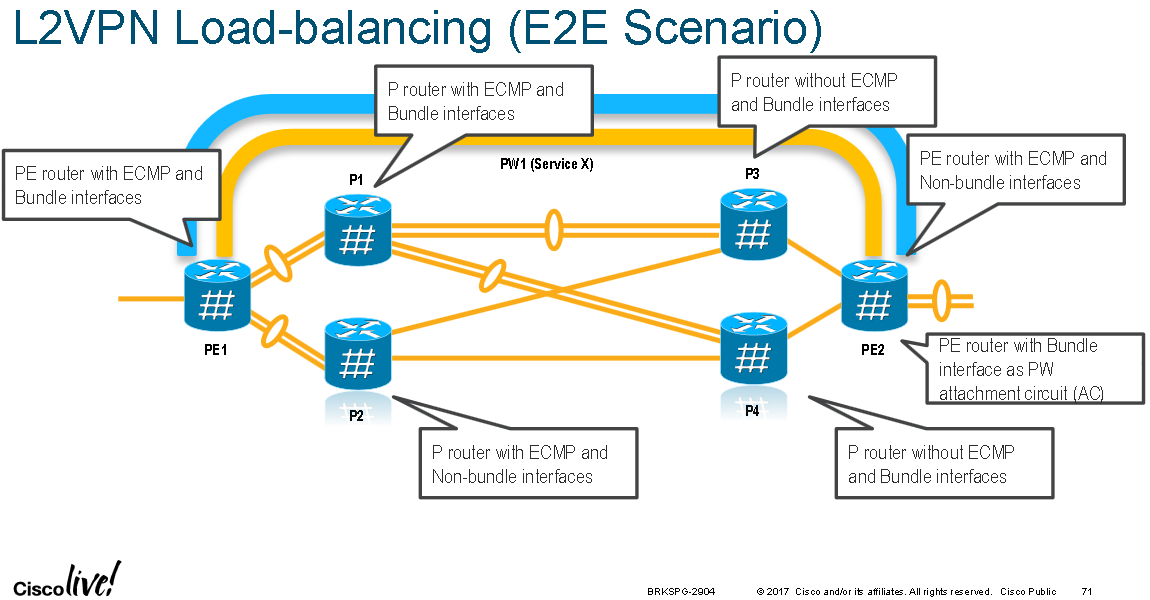
When traffic enters an LER that is part of a L2 VPN there are three places that hashing can be configured (at the ingress bundle interface level [if there is one, it might just be a single ingress interface], at the l2vpn level, and at the egress pseudowire level) with an order of preference; this is shown in the two diagrams below:
The following diagram summaries available load-balancing settings:
MPLS P Node Hashing Specifics
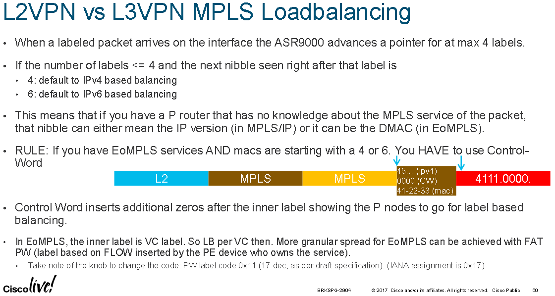
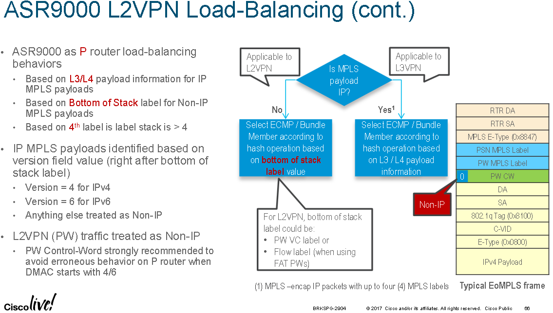
ASR9000 MPLS P nodes look at the first nibble directly after the BoS MPLS label to determine if the VPN payload is layer 2 or layer 3. If the first nibble is 4 or 6 is it assumed to be IPv4/IPv6. If it is 0 it is assumed to be a pseudowire control-world and an Ethernet header follows the control-word. Any other value is assumed to be a destination MAC address directly following the BoS label.
The problem with this approach is that some MAC addresses start with 0 in the first nibble. An MPLS P node may not be able to tell if the first nibble represents a destination MAC is starting with 0 in the first nibble or a control-word. The LER/PE nodes will know because the use of the control-word is negotiated during pseudowire set-up signalling.
ASR9000 P nodes are also only able to look up to and including 4 labels deep, if the fourth label isn't the BoS label then hashing is performed based on the 4th label. If there are 4 or less labels then the first nibble after the bottom label is inspected. If the first nibble is a 4 or 6 then then the egress path hash is calculated based upon the layer 3 / layer 4 headers inside the L3 VPN. Any other nibble value is assumed to represent a layer 2 VPN and the last label is used as the hash value. If there are four or less MPLS labels this could be the pseudowire VC label (so all traffic on the same VC will take the same ECMP/LAG paths) or a flow label when using FAT pseudowires (so that flows within the same VC will be distributed across available ECMP/LAG paths).
It is possible to hash based on the top MPLS label in a stack, also known as implementing Top Label Hashing when using ASR9K/IOS-XR. This can be used to provide predictable hashing when using link bundles for core MPLS links. This means that the transport label is used and as such flows between the same source and destination PE would always hash onto the same bundle member. However, this is only supported with static LSPs on IOS-XR and the ASR9000 series.
One can test the CEF load-balancing result for MPLS labelled traffic by using the following command:
# Testing MPLS label(s) and optionally layer 3 VPN payload IPs on IOS-XR 5.3.3-SP4
RP/0/RSP0/CPU0:ASR9001#show mpls forwarding exact-route label 12345 ipv4 1.1.1.1 2.2.2.1

RP/0/RSP0/CPU0:ASR9001#show mpls forwarding exact-route label 12345 ?
  bottom-label   Bottom label
  entropy-label  Entropy label
  ipv4           Exact path for IPv4 payload
  ipv6           Exact path for IPv6 payload
The "bottom-label" can be the VC label for a L2 VPN or a layer 3 VPN label.
Note: "...in case of trident [linecards] there is a known behaviour [limitation] of MPLS hashing on bundle interfaces. If a bundle interface has an even number of member links, the MPLS hash would cause only half of these links to be utilized. To get around this, you may have to configure "cef load-balancing adjust 3" command on the router. Or use odd number of member links within the bundle interface. Note that this limitation applies only to trident line cards..."
Bugs/Enhancements CSCvg35000 and CSCvg34997 bring support for hashing on label stacks larger than 4 labels (from 5 to 8 labels deep) to support SR-TE.
MPLS PE Node Hashing Specifics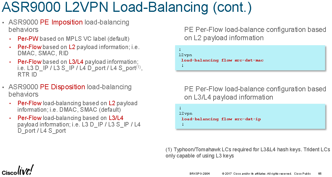
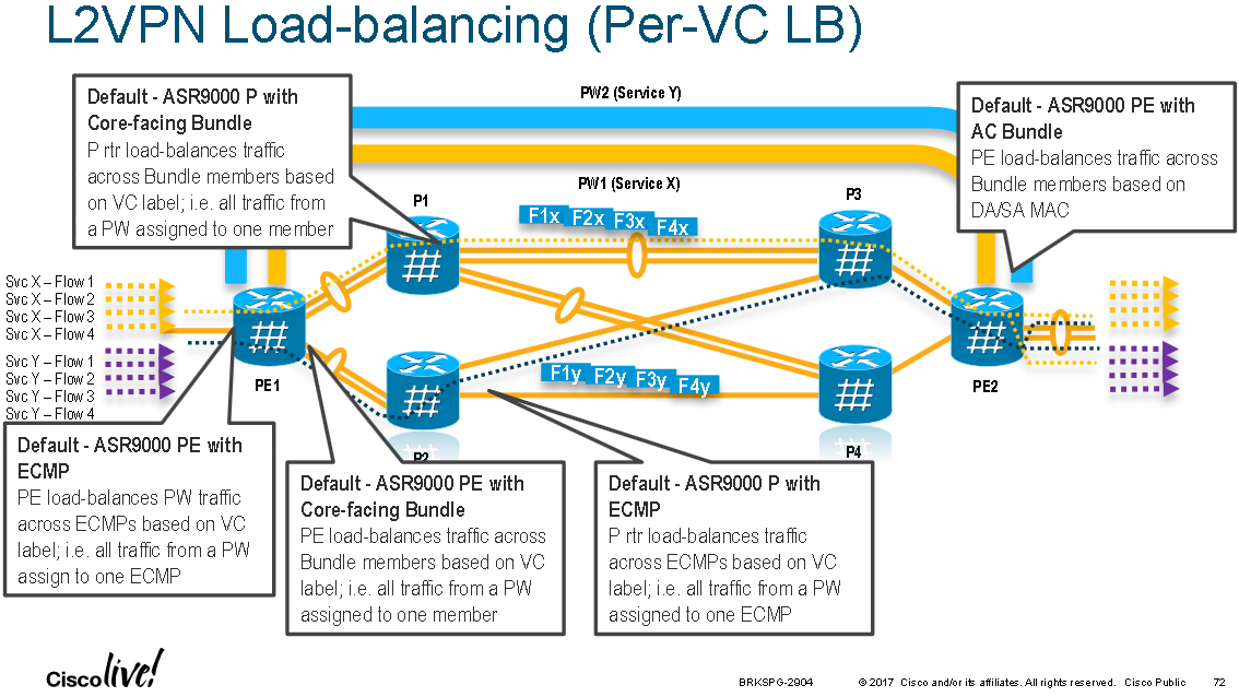
PE's perform hashing at ingress for L2 and L3 VPNs. For L2 VPNs the hashing is configured at one of three levels, in reverse priority order they are:
1. At the L2VPN sub-configuration mode with "load-balancing flow" command with the following options:
RP/0/RSP1/CPU0:ASR9000(config-l2vpn)# load-balancing flow ?
src-dst-ip
src-dst-mac [default]
2. At the pw-class sub-configuration mode with "load-balancing" command with the following options:
RP/0/RSP1/CPU0:ASR9000(config-l2vpn-pwc-mpls-load-bal)#?
flow-label [see FAT Pseudowire section]
pw-label [per-VC load balance]
3. At the Bundle interface sub-configuration mode with "bundle load-balancing hash" command with the following options:
RP/0/RSP1/CPU0:ASR9000(config-if)#bundle load-balancing hash ? [For default, see previous sections]
dst-ip
src-ip
Note: 1 is weaker than 2 which is weaker than 3.
Flow Aware Transport Pseudowires
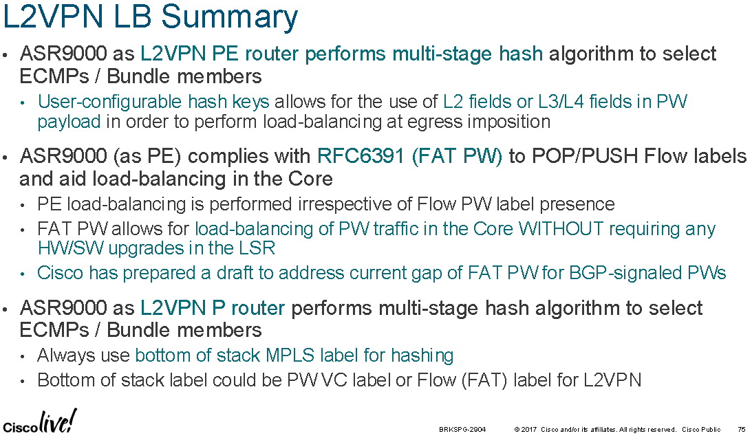
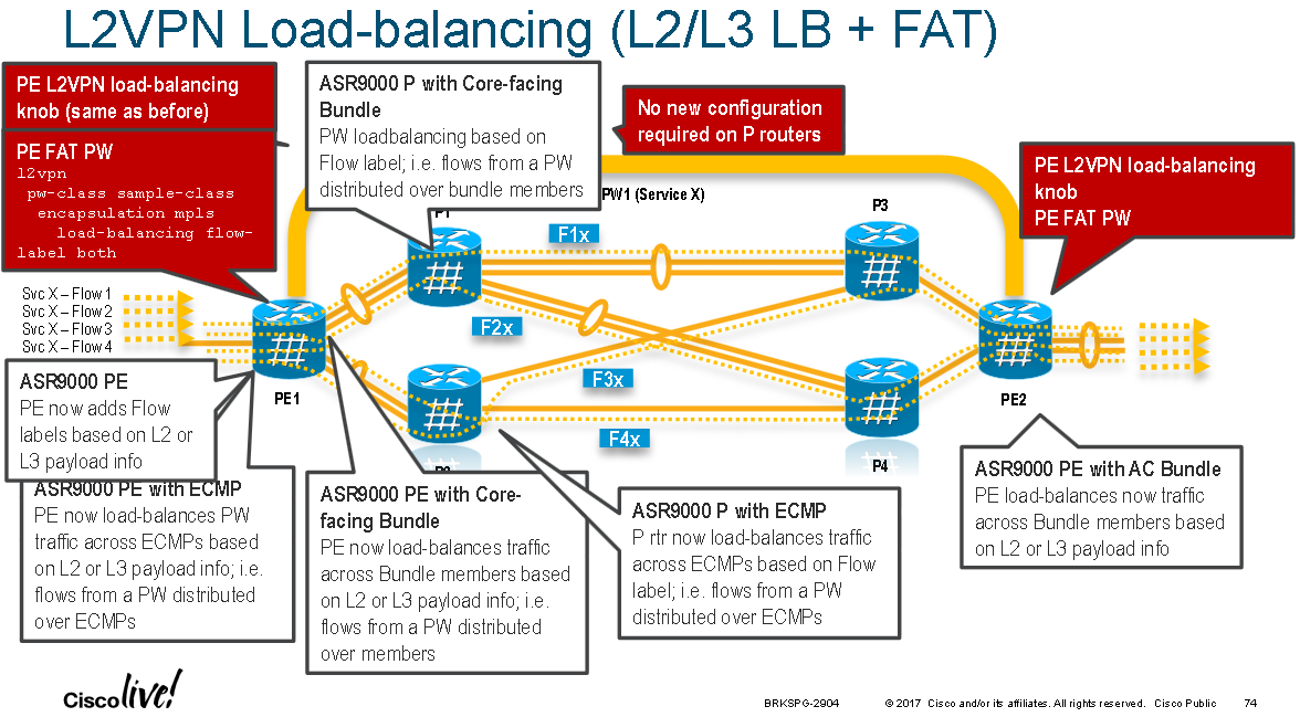
FAT Pseudowires are supported in IOS-XR on the ASR9000 series devices from version 4.2.1 onwards. FAT pseudowires insert a new BoS label which is calculated by hashing the headers of L2 VPN frames at the ingress PE and calculating a label value that is unique to each flow within the L2 VPN. The goal is to provide P nodes along the path with more entropy information so that they can improve load distribution across ECMP/LAG links for the L2 VPN traffic without having to support the protocols being transported within the L2 VPN.
By default the source and destination MAC addresses are hashed but optionally layer 3 source and destination IP addresses can be configured as the input to the calculation. IPv6 wasn't supported as the layer 3 hash fields until IOS-XR 4.3.something(?).
PE nodes insert this extra label at the bottom of the MPLS stack which is unique to the flow being transported over the L2 VPN. ASR9000 P nodes along the path which hash based on the BoS label for L2 VPNs (if the label stack is less than or equal to 4 labels or simply the 4th label if it is greater than 4 labels) will now hash on this flow specific label. This means that multiple flows running over the same L2 VPN will take different ECMP/LAG paths across the network to distribute the load and within each flow the same path is always used to help prevent frame miss-ordering.
ASR9000's will calculate the FAT label and check that it isn't a reserved label value or an existing value used for another purpose.
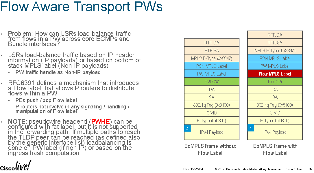
Note: FAT labels are not supported with PWHE even though it is configureable.
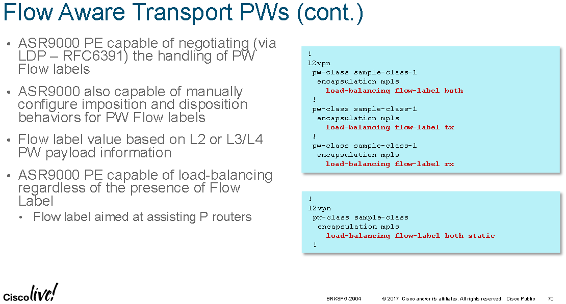
Note: The ingress PE and egress PE must support FAT labels and negotiate this capability when setting up the L2 VPN using LDP for signalling. BGP signalling for L2 VPNs with FAT is not supported.
Config options from 5.3.3-SP4 are shown below:
RP/0/RSP0/CPU0:ASR9001(config)#l2vpn
RP/0/RSP0/CPU0:ASR9001(config-l2vpn)#pw-class pwe3-fat-class encapsulation mpls
RP/0/RSP0/CPU0:ASR9001(config-l2vpn-pwc-mpls)#load-balancing ?
  flow-label  Flow label based load balancing setting
  pw-label    Enable Flow based load balancing
RP/0/RSP0/CPU0:ASR9001(config-l2vpn-pwc-mpls)#load-balancing
RP/0/RSP0/CPU0:ASR900(config-l2vpn-pwc-mpls-load-bal)#flow-label ?
  both      Insert/Discard Flow label on transmit/receive
  code      Flow label TLV code
  receive   Discard Flow label on receive
  transmit  Insert Flow label on transmit
In the following config example the "load-balancing flow src-dst-ip" configures the PE to hash incoming L2 VPN traffic from the local access circuit, towards the MPLS enabled core, based on layer 3 IP addresses instead of the default layer 2 MAC address information. Under the pseudowire class FAT label imposition and disposition is then enabled for "both" incoming and outgoing packets across any L2 VPN to which the PWE3 class is applied. The FAT label imposition occurs after the hash is calculated. In this example the l2vpn "load-balancing" command will cause the FAT label to be calculated on layer 3 address instead of the default behaviour which is to use layer 2 addresses. This means that FAT labels are calculated in the same way the hashing is done (either at layer 2 or layer3/4):
RP/0/RSP0/CPU0:ASR9001(config)#l2vpn
RP/0/RSP0/CPU0:ASR9001(config-l2vpn)#load-balancing flow src-dst-ip
RP/0/RSP0/CPU0:ASR9001(config-l2vpn)#pw-class 123
RP/0/RSP0/CPU0:ASR9001(config-l2vpn-pwc)#encapsulation mpls
RP/0/RSP0/CPU0:ASR9001(config-l2vpn-pwc-mpls)#load-balancing flow-label both
0x17 is the Sub-TLV type assigned for Flow Label mappings by IANA for LDP when signalling flow aware label mappings "FL Sub-TLV". Originally 0x11 was assigned in RFC6391 "Flow-Aware Transport of Pseudowires over an MPLS Packet Switched Network" when it was a draft. IANA later assigned 0x17 when the draft became a standard. IOS-XR version 4.3.1 and earlier use 0x11 for signalling FAT labels and 4.3.2 and newer use 0x17. To interoperate between these two version one can manually specify the flow label TLV value under a pseudowire class. Below a 4.3.2 or newer version of IOS-XR is configured to use 0x11 to interop with an older IOS-XR version. The confusing point of note here is that "17" below is 0x11 in deanery:
l2vpn
 pw-class 123
  encapsulation mpls
   load-balancing
    flow-label code 17
Troubleshooting
Use "show cef X.X.X.X/Y detail" to see the load-distribution amongst hash buckets when using UCMP.
Check on the ingress and egress line card that for the same destination prefix the num_entries value is the same, to ensure that the ingress and egress card see the same number of paths and aren't hashing traffic into non-existing buckets: "show cef XX.XX.XX.XX hardware egress detail location 0/1/cpu0"
Previous page: TTCP Testing
Next page: BFD