Date created: Thursday, May 25, 2017 10:35:00 AM. Last modified: Monday, June 10, 2024 12:22:14 PM
Encoding Schemes
References
http://www.tested.com/tech/457440-theoretical-vs-actual-bandwidth-pci-express-and-thunderbolt/
https://en.wikipedia.org/wiki/8b/10b_encoding
https://en.wikipedia.org/wiki/64b/66b_encoding
https://en.wikipedia.org/wiki/PCI_Express
http://www.erg.abdn.ac.uk/users/gorry/course/lan-pages/1000bt.html
https://en.wikipedia.org/wiki/Manchester_code
https://superuser.com/questions/457775/why-do-we-need-to-use-manchester-encoding-for-ethernet-transmissions
Contents:
Manchester Coding
8b/10b Encoding
64b/66b Encoding
128b/130b Encoding
Relation to Networking
Manchester Coding
Manchester coding (also known as phase encoding, or PE) is a line code in which the encoding of each data bit is either low then high, or high then low, of equal time. It therefore has no DC bias, and is self-clocking, meaning the clock signal can be recovered from the encoded data. Manchester code ensures frequent line voltage transitions, directly proportional to the clock rate; this helps clock recovery. The DC component of the encoded signal is not dependent on the data and therefore carries no information, allowing the signal to be conveyed conveniently by media (e.g., Ethernet) which usually do not convey a DC component.
Manchester encoding is a special case of binary phase-shift keying (BPSK), where the data controls the phase of a square wave carrier whose frequency is the data rate. Such a signal is easy to generate.
Manchester code always has a transition at the middle of each bit period and may (depending on the information to be transmitted) have a transition at the start of the period also. The direction of the mid-bit transition indicates the data. Transitions at the period boundaries do not carry information. They exist only to place the signal in the correct state to allow the mid-bit transition. The existence of guaranteed transitions allows the signal to be self-clocking, and also allows the receiver to align correctly; the receiver can identify if it is misaligned by half a bit period, as there will no longer always be a transition during each bit period. The price of these benefits is a doubling of the bandwidth requirement compared to simpler NRZ coding schemes (10BASE-T which uses Manchester coding for example, has a clock rate of 20Mhz which is double the speed required to simply electrically pulse 10 million bits per second if a separate clock channel/wire existing).

Extracting the original data from the received encoded bit (from Manchester as per 802.3):
- Each bit is transmitted in a fixed time (the "period").
- A 0 is expressed by a low-to-high transition, a 1 by high-to-low transition (according to G.E. Thomas' convention—in the IEEE 802.3 convention, the reverse is true).
- The transitions which signify 0 or 1 occur at the midpoint of a period.
- Transitions at the start of a period are overhead and don't signify data.
There are two opposing conventions for the representations of data. The first by G. E. Thomas specifies that for a 0 bit the signal levels will be low-high (assuming an amplitude physical encoding of the data) - with a low level in the first half of the bit period, and a high level in the second half. For a 1 bit the signal levels will be high-low.
The second convention is used by IEEE 802.4 (token bus) and lower speed versions of IEEE 802.3 (Ethernet) standards. It states that a logic 0 is represented by a high-low signal sequence and a logic 1 is represented by a low-high signal sequence.
8b/10b Encoding
In telecommunications, 8b/10b is a line code that maps 8-bit words to 10-bit symbols to achieve DC-balance and bounded disparity, and yet provide enough state changes to allow reasonable clock recovery. This means that the difference between the counts of ones and zeros in a string of at least 20 bits is no more than two, and that there are not more than five ones or zeros in a row. This helps to reduce the demand for the lower bandwidth limit of the channel necessary to transfer the signal.
As the scheme name suggests, eight bits of data are transmitted as a 10-bit entity called a symbol, or character. The low five bits of data are encoded into a 6-bit group (the 5b/6b portion) and the top three bits are encoded into a 4-bit group (the 3b/4b portion). These code groups are concatenated together to form the 10-bit symbol that is transmitted on the wire. Standards using the 8b/10b encoding also define up to 12 special symbols (or control characters) that can be sent in place of a data symbol. They are often used to indicate start-of-frame, end-of-frame, link idle, skip and similar link-level conditions. At least one of them (i.e. a "comma" symbol) needs to be used to define the alignment of the 10 bit symbols.
Because 8b/10b encoding uses 10-bit symbols to encode 8-bit words, some of the possible 1024 (10 bit, 2^10) codes can be excluded to grant a run-length limit of 5 consecutive equal bits and to achieve the difference of the count of zeros and ones to be no more than two. Some of the 256 possible 8-bit words can be encoded in two different ways. Using these alternative encodings, the scheme is able to achieve long-term DC-balance in the serial data stream.
8b/10b coding is DC-free, meaning that the long-term ratio of ones and zeros transmitted is exactly 50%. To achieve this, the difference between the number of ones transmitted and the number of zeros transmitted is always limited to +/- 2, and at the end of each symbol, it is either +1 or −1. This difference is known as the running disparity (RD).
The 5b/6b code is a paired disparity code, and so is the 3b/4b code. Each 6- or 4-bit code word has either equal numbers of zeros and ones (a disparity of zero), or comes in a pair of forms, one with two more zeros than ones (four zeros and two ones, or three zeros and one one, respectively) and one with two less. When a 6- or 4-bit code is used that has a non-zero disparity (count of ones minus count of zeros; i.e., −2 or +2), the choice of positive or negative disparity encodings must be the one that toggles the running disparity. In other words, the non zero disparity codes alternate.
For each 5b/6b and 3b/4b code with an unequal number of ones and zeros, there are two bit patterns that can be used to transmit it: one with two more "1" bits, and one with all bits inverted and thus two more zeros. Depending on the current running disparity of the signal, the encoding engine selects which of the two possible six- or four-bit sequences to send for the given data. Obviously, if the six-bit or four-bit code has equal numbers of ones and zeros, there is no choice to make, as the disparity would be unchanged, with the exceptions of sub-blocks D.07 (00111) and D.x.3 (011). In either case the disparity is still unchanged, but if RD is positive when D.07 is encountered, use 000111, and if it's negative use 111000. Likewise, if RD is positive when D.x.3 is encountered use 0011, and if it's negative use 1100.
Note that 8b/10b is the encoding scheme, not a specific code. While many applications do use the same code, there exist some incompatible implementations; for example, Transition Minimized Differential Signaling, which also expands 8 bits to 10 bits, but it uses a completely different method to do so.
Technologies that use 8b/10b:
- DVI and HDMI
- Fibre Channel
- Gigabit Ethernet (except for the twisted pair–based 1000Base-T)
- Infiniband
- Serial ATA
- SGMII
- SAS
- USB 3.0
- XAUI
RP/0/RSP0/CPU0:ASR9000#show controllers gi0/0/0/5 phy
SFP EEPROM  port: 5
        Xcvr Type: SFP
        Xcvr Code: 1000BASE-LX
        Encoding: 8B10B
        Bit Rate: 1300 Mbps
64b/66b Encoding
In data networking and transmission, 64b/66b is a line code that transforms 64-bit data to 66-bit line code to provide enough state changes to allow reasonable clock recovery and facilitate alignment of the data stream at the receiver. It was defined by the IEEE 802.3 working group as part of the IEEE 802.3ae-2002 amendment which introduced 10 Gbit/s Ethernet.
The protocol overhead of a coding scheme is the ratio of the number of added coding bits to the number of raw payload bits. The overhead of 64b/66b encoding is 2 overhead bits for every 64 raw bits transmitted or 3.125%. This is considerably more efficient than the 25% overhead of the previously used 8b/10b encoding scheme which essentially charges every 8 bits of source data with a 2 bit (or 25%) tax. At the time 64b/66b was deployed, it allowed 10 Gb Ethernet to be transmitted with the same lasers used by SONET OC-192, rather than requiring 12.5 Gbit/s lasers, which were not expected to become available for several years.
The overhead can be reduced further by doubling the block size to produce 128b/130b encoding, as used by PCIe 3.0 (2/130 = 1.54%), and a very similar variant is the 128b/132b encoding used by USB 3.1.
64b/66b encoding, introduced for 10 Gigabit Ethernet's 10GBASE-R Physical Medium Dependent (PMD) interfaces, is a lower-overhead alternative to 8b/10b encoding, having a two-bit overhead per 64 bits (instead of eight bits) of encoded data. This scheme is considerably different in design from 8b/10b encoding, and does not explicitly guarantee DC balance, short run length, and transition density (these features are achieved statistically via scrambling).
The 66 bit entity is made by prefixing one of two possible two-bit preambles to the 64 bits to be transmitted.
- If the preamble is 01, the 64 bits are entirely data.
- If the preamble is 10, an eight-bit type field follows, plus 56 bits of control information and/or data.
- The preambles 00 and 11 are not used, and generate an error if seen.
The use of the 01 and 10 preambles guarantees a bit transition every 66 bits, which means that a continuous stream of 0s or 1s cannot be valid data. It also allows easier clock/timer synchronization, as a transition must be seen every 66 bits.
The complete payload (consisting of either 64 data bits, or an 8-bit type and 56 data bits) is scrambled using a self-synchronous scrambler function, with the intention of ensuring that a relatively even distribution of 1s and 0s are normally found in the transmitted data. The intention is not to encrypt the data, but to give the transmitted data useful engineering properties. The scrambler does not provide an absolute guarantee that output data will never have a long run-length of 0s or all 1s or other undesirable properties, but instead allows strong statistical bounds to be put on the probability of such events. Practical designs will choose system parameters such that a bit-error due to long run-lengths is vanishingly unlikely. This method is different from the codebook based approach of 8b/10b encoding.
The encoding and scrambling are normally done entirely in hardware, the scrambling using a linear feedback shift register. Upper layers of the software stack need not be aware that the link layer is using this code.
A variation of 64b/66b exists in the Interlaken protocol which improves the DC balance further by trading off more coding bits. 64b/67b encoding provides explicit DC balancing.
Technologies that use 64b/66b encoding:
- 10 Gigabit Ethernet (most varieties)
- Fibre Channel 10GFC and 16GFC
- 100 Gigabit Ethernet
- 10G-EPON, 10 Gbit/s Ethernet Passive Optical Network
- Aurora, from Xilinx
- InfiniBand
- Thunderbolt
- Common Public Radio Interface
RP/0/RSP0/CPU0:ASR9000#show controllers Te0/0/1/1 phy
XFP EEPROM  port: 1
        Xcvr Type: XFP
        Connector Type: LC
        Ethernet Xcvr Codes: 10GBASE-LR,
        SONET Xcvr Codes:
        Encodeing: 64B/66B, SONET Scrambled, NRZ,
        Bit Rate Min.: 9900 Mbit/s
        Bit Rate Max.: 11100 Mbit/s
        Link Reach 9u SM fiber: 10 Km
        Device Tech.: 1310 nm DFB, No wavelength ctrl, Uncooled Xmtr, PIN detector, Xmtr not tunable,
        CDR Support: 9.95 Gb/s, 10.3 Gb/s, 10.5 Gb/s, 10.7 Gb/s, 11.1 Gb/s,
128b/130b Encoding
PCI Express 3.0 introduced 128b/130b encoding, which is similar to 64b/66b but has a payload of 128 bits instead of 64 bits, and uses a different scrambling polynomial. It is also not self-synchronous and so requires explicit synchronization of seed values, in contrast with 64b/66b.
USB 3.1 uses 128b/132b encoding, which is identical to 128b/130b, but duplicates each of the preamble bits to reduce the risk of undetected errors there.
PCIe 1.* and 2.0 use 8b/10b encoding (like SATA does), so they lose 20 percent of their theoretical bandwidth to overhead. After overhead, the maximum per-lane data rate of PCIe 1.0 is eighty percent of 2.5GT/s. That gives us two gigabits per second, or 250MB/s (remember, eight bits to a byte). The PCIe interface is bidirectional, so that's 250MB/s in each direction, per lane. PCIe 2.0 doubles the per-lane throughput to 5GT/s, which gives us 500MB/s of actual data transfer per lane.
PCIe 3.0's per-lane theoretical throughput is 8GT/s which is 60 percent more than PCIe 2.0's 5GT/s. That's because PCIe 3.0 and above use a more efficient encoding scheme called 128b/130b so the overhead is much less - only 1.54%. That means that a single PCIe 3.0 lane, at 8GT/s, can send 985MB/s. Not quite twice 500MB/s.
Technologies that use 128b/13xb encoding:
- PCIe 3.0
- USB 3.1
- SATA 3.2
- NVLink 1.0
Relation to Networking
PCI Express 3.0's 8 GT/s bit rate effectively delivers 985 MB/s per lane. 985MBps * 8 = 7880Mbps per PCIe 3.0 lane. This means that a PCIe 3.0 1x card (meaning one lane) could not support a 10GE NIC at line rate. A PCIe 3.0 4x lane card would be required (4 lanes is the next interval up from 1 lane, PCIe 3.0 2x "2 lane cards" for example, do not exist).
8GT/s per lane = 80000000000 bits * (128/130 * 100) = 7876800000000 / 1000 / 1000 / 1000 = 7876.8Mbps / 8 = 984.6MBps
With 10GE NICs multiple PCIe 3.0 lanes can be used, each lane is a "dumb" serial lane and a SerDes that runs at 10Gbps or faster can be used to multiplex multiple 8GT/s lanes serially thus maintaining packet order over the PCIe connection.
Most 10GBASE-X fibre standards use 64b/66b encoding which means that due to the 3.125% overhead of 64b/66b encoding most transceivers run at 10.3125 Gbit/s. 10GBASE-T used pulse-amplitude modulation with 16 discrete levels (PAM-16) compared to 1000BASE-T's PAM-5 (four levels which represents to binary bits plus a parity level).
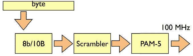
The various 1000BASE-X fibre standards use 8b/10b encoding which means that due to the 25% overhead of 8b/10b transceivers actually run at 1.25Gbps. With 1000BASE-T copper 1GigE connections, 8b/10b is used but then pairs of bits are encoded using PAM-5. 5-level PAM provides better bandwidth utilization than binary signalling, where each transmitted symbol represents just one bit (0 or 1.). In 5-level PAM, each transmitted symbol represents one of five different levels (-2, -1, 0, + 1, +2). Since each symbol can represent two bits of information (four levels used to represent two bits, plus an extra fifth level used in the Forward Error Correction coding), the symbol rate, and therefore also the signal bandwidth, are reduced by a factor of two.
1000BASE-T uses four twisted copper pairs over Cat5 cable.
100BASE-TX uses 4B5B MLT-3 coded signalling and over twisted pairs in Cat5 copper cable.
10BASE-T uses Manchester coded signalling over two twisted pairs in Cat3 or Cat5 copper cable.
Why use any of these coding schemes for networking? Some reasons include:
- With Manchester coding the data and clock are combined into one signal (such as 10BASE-T). If the clock was not sent with the data, then the receiver would not know when to sample the signal to extract the digital values. Even if the transmitter and receiver are somehow perfectly synchronized, the infinitesimal delay of the transmission medium would have to be accounted for. The other alternative is to accompany the data line with a clock line, but that doubles the number of wires. It's cheaper & more reliable to double (or halve, depending on perspective) the cable & transceiver bandwidth requirements (or capabilities) than use more wire and bulkier connectors.
With other encoding schemes like 64b/66b and 128b/130b the clock signal is calculated using a polynomial feedback function on the receiver to statistically calculate the clocking (such as 10GBASE-X). - A long string of zeroes will no longer look like a dead or disconnected line. Also long sting of ones will no longer look like a stuck level. This issue is overcome in Manchester, 8b10b, 64b/66b and 128b/130b encoding techniques.
- With Manchester and 8b/18b (10BASE-T, 1000BASE-T) encoding the encoded signal has a more balanced energy profile, i.e. the voltage averaged over time should tend toward zero. The logic signal on the circuit board uses 0 volts for logic zero and a positive voltage (5 volts for old TTL, 3.3 volts or less for modern logic) for logic one. Only data logic of all zeros would have a null energy profile; any other data pattern would always have a greater than zero average voltage level and a characteristic magnetic field. But since encodings such as Manchester use both positive and negative voltage levels, the magnetic fields created by the transmitted signal are much smaller as they will tend to cancel each other. This allows wires to be bundled closer together in cables yet create less interference with each other. (Even slow transmission schemes like RS/EIA-232 use both positive and negative voltage levels to balance the energy profile. Probably board-to-board connections less than 0.5 meter and within an enclosure would use only positive voltages.)
Previous page: CRC and Checksum Error Detection
Next page: Forwarding Hardware