Date created: Thursday, November 8, 2018 9:14:10 PM. Last modified: Sunday, November 18, 2018 11:49:09 AM
Explicit Path Interop (IOS-XR and Junos)
References:
https://www.juniper.net/documentation/en_US/junos/topics/task/configuration/make-before-break-achieving-for-lsps.html
https://www.juniper.net/documentation/en_US/junos/topics/usage-guidelines/mpls-configuring-adaptive-lsps.html
Contents:
Lab Topology
RSVP-TE Recap
Partial Device Configs
Explicit Path Device Outputs
Dynamic Path Device Outputs
Additional Outputs
Full Device Configs
Lab Topology:
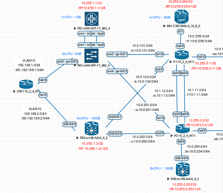
A basic example of an explicit path between Cisco IOS-XR (ASR9K-XRv 6.4.2) and Juniper Junos (vMX 17.4R2). Below is the lab topology, the explicit path shall run from PE1 (Junos, top left) to P1 (top right), to P2 (bottom right), to PE2 (IOS-XRv, bottom left) and a reverse explicit path from PE2 to PE1 runs along the same path. A dynamic backup shall also be configured on both PEs. If the explicit path becomes available, the dynamic path will be used. No constraints have been configured so CSPF is not being used, the backup dynamic tunnel shall simply follow the IGP shortest path. IS-IS is running with TE enabled, MPLS and RSVP have been enabled on all interfaces of all devices. Assume that IS-IS is fully converged. The shortest path between PE1 and PE2 is either PE1 > P1 > PE2 or PE1 > P2 > PE2, all links have a default metric of 10:
On Junos TE extensions are enabled in IS-IS by default, they are disabled in OSPFv2 by default. In IOS and IOS-XR TE extensions are disabled by default in IS-IS and OSPFv2.
Junos sees 100% of interface bandwidth as available but reserves none by default. IOS-XR see 75% of interface bandwidth available and reserves none by default.
root@PE1> show rsvp interface
RSVP interface: 2 active
                          Active  Subscr- Static      Available   Reserved    Highwater
Interface          State  resv    iption  BW          BW          BW          mark
ge-0/0/1.0             Up       1   100%  1000Mbps    1000Mbps    0bps        0bps
ge-0/0/2.0             Up       0   100%  1000Mbps    1000Mbps    0bps        0bps
RP/0/RP0/CPU0:PE2#show rsvp interface
Sat Nov 10 08:41:11.952 UTC

*: RDM: Default I/F B/W % : 75% [default] (max resv/bc0), 0% [default] (bc1)

Interface                 MaxBW (bps)  MaxFlow (bps) Allocated (bps)      MaxSub (bps)
------------------------- ------------ ------------- -------------------- -------------
GigabitEthernet0/0/0/2              0              0             0 (  0%)            0
GigabitEthernet0/0/0/1              0              0             0 (  0%)            0
Junos and IOS-XR don’t reoptimse RSVP-TE tunnels by default. In Junos one can use the following configuration to implement make-before-break (MBB) RSVP LSPs, which is only required on the ingress PE (because all RSVP LSPs are signalled by the head-end LER):
# Time in seconds to periodically refresh RSVP LSPs
set protocols mpls optimize-timer T1
# Time in seconds to new LSP must be up before traffic is moved to new LSP
set protocols mpls optimize-switchover-delay T2
# Time in seconds to wait after traffic switchover to new LSP before tearing down old LSP
set protocols mpls optimize-hold-dead-delay T3
In Junos one can enable the adaptive knob which allows an RSVP LSP to hold the resources allocated on the original LSP until all traffic is moved to the new LSP before releasing them:
set protocols mpls label-switched-patch NAME adaptive
The equivalent IOS-XR timers are (in the above order):
mpls traffic-end reoptimize T1
mpls traffic-eng reoptimize timers delay installation T2
mpls traffic-eng reoptimize timers delay cleanup T3
The problem with the above approach to MBB on Junos is that the process is timer based. After timer T1 has expired a new LSP may have been signalled depending on how busy the P nodes are along the new path, and after T2 has expired traffic may be moved over to the new LSP even though end-to-end forwarding might not be working yet, and after T3 has expired not all traffic may have been fully migrated to the new LSP before the old LSP will be torn down, resulting in traffic lost. RSVP LSP refresh needs to be event based and not timer based.
As of Junos 15.1 the optimize-adaptive-teardown knob was added. This feature supports RSVP P2P LSPs only. Once enabled the optimize-switchover-delay and optimize-hold-dead-delay timers knob aren’t required (the adaptive knob could still be useful though). This knob enables LSP-ping (which means lo0 filters must be updated!) to ensure the end-to-end forwarding path is working before traffic is moved to the new LSP. It also uses feedback from RPD to ensure that the old LSP isn’t torn down until all traffic is moved to the new LSP:
set protocols mpls optimize-adaptive-teardown p2p
This MBB behaviour is enabled by default on IOS-XR.
Relevant PE1 config snippet:
set interfaces ge-0/0/1 unit 0 description P1-Fa1/0
set interfaces ge-0/0/1 unit 0 family inet address 10.0.101.2/24
set interfaces ge-0/0/1 unit 0 family iso
set interfaces ge-0/0/1 unit 0 family inet6 address ::d:10:0:101:2/64
set interfaces ge-0/0/1 unit 0 family mpls
set interfaces ge-0/0/2 unit 0 description P2-Fa1/0
set interfaces ge-0/0/2 unit 0 family inet address 10.0.201.2/24
set interfaces ge-0/0/2 unit 0 family iso
set interfaces ge-0/0/2 unit 0 family inet6 address ::a:10:0:201:2/64
set interfaces ge-0/0/2 unit 0 family mpls
set interfaces ge-0/0/3 description CPE1-Fa0/0
set interfaces ge-0/0/3 vlan-tagging
set interfaces ge-0/0/3 encapsulation flexible-ethernet-services
set interfaces ge-0/0/3 unit 10 vlan-id 10
set interfaces ge-0/0/3 unit 10 family inet address 192.168.1.1/24
set interfaces ge-0/0/3 unit 10 family inet6 address ::65:192:168:1:1/64
set interfaces lo0 unit 0 family inet address 10.255.1.1/32
set interfaces lo0 unit 0 family iso address 49.0001.0102.5500.1001.00
set interfaces lo0 unit 0 family inet6 address ::ffff:10:255:1:1/128
set protocols rsvp interface ge-0/0/1.0
set protocols rsvp interface ge-0/0/2.0
set protocols mpls optimize-adaptive-teardown p2p   # Enable make-before-break
set protocols mpls icmp-tunneling                   # Show P/PE nodes in ICMP traceroutes for debugging
set protocols mpls label-switched-path PE1>PE2 to 10.255.1.2
set protocols mpls label-switched-path PE1>PE2 install 10.255.1.2/32 active
set protocols mpls label-switched-path PE1>PE2 record
set protocols mpls label-switched-path PE1>PE2 primary PE1_P1_P2_PE2
set protocols mpls label-switched-path PE1>PE2 secondary PE2
set protocols mpls path PE2 10.255.1.2 loose        # Without the "loose" keyword this won't work as 10.255.1.2 isn't directly connected to any interface
set protocols mpls path PE1_P1_P2_PE2 10.0.101.1 strict
set protocols mpls path PE1_P1_P2_PE2 10.1.12.2 strict
set protocols mpls path PE1_P1_P2_PE2 10.0.202.2 strict
set protocols mpls path PE1_P1_P2_PE2 10.255.1.2 strict
set protocols mpls interface ge-0/0/1.0
set protocols mpls interface ge-0/0/2.0
set protocols isis level 2 wide-metrics-only    # Must use wide metrics for TE
set protocols isis level 1 disable
set protocols isis interface ge-0/0/1.0 point-to-point
set protocols isis interface ge-0/0/1.0 level 1 disable
set protocols isis interface ge-0/0/2.0 point-to-point
set protocols isis interface ge-0/0/2.0 level 1 disable
set protocols isis interface lo0.0 passive
Relevant PE2 config snippet:
group e-te-tun
 interface 'tunnel-te10.*'
  ipv4 unnumbered Loopback0      ! This can be specified at the group level, individual interface level or globally
  autoroute announce
  !
  record-route
  path-option 100 dynamic
 !
end-group
!
explicit-path name PE2_P2_P1_PE1
 index 10 next-address strict ipv4 unicast 10.0.202.1
 index 20 next-address strict ipv4 unicast 10.1.12.1
 index 30 next-address strict ipv4 unicast 10.0.101.2
 index 40 next-address strict ipv4 unicast 10.255.1.1
!
ipv4 unnumbered mpls traffic-eng Loopback0  ! This can be defined here for all tunnels globally, or
! directly under a tunnel interface or "group" stanza
!
interface Loopback0
 ipv4 address 10.255.1.2 255.255.255.255
 ipv6 address ::ffff:10:255:1:2/128
!
interface tunnel-te1001
 apply-group e-te-tun
 description To PE1
 signalled-name PE2_P2_P1_PE1
 logging events all
 destination 10.255.1.1
 path-option 10 explicit name PE2_P2_P1_PE1
!
interface GigabitEthernet0/0/0/1
 description P1-Fa2/0
 ipv4 address 10.0.102.2 255.255.255.0
 ipv6 address ::b:10:0:102:2/64
!
interface GigabitEthernet0/0/0/2
 description P2-Fa2/0
 ipv4 address 10.0.202.2 255.255.255.0
 ipv6 address ::c:10:0:202:2/64
!
interface GigabitEthernet0/0/0/3
 description CPE1-Fa1/0
!
interface GigabitEthernet0/0/0/3.10
 vrf CPE1
 ipv4 address 192.168.2.1 255.255.255.0
 ipv6 address ::66:192:168:2:1/64
 encapsulation dot1q 10
!
router isis 1
 is-type level-2-only
 net 49.0001.0102.5500.1002.00
 log adjacency changes
 log pdu drops
 address-family ipv4 unicast
  metric-style wide
  mpls traffic-eng level-2-only      ! TE must be explicitly enabled for IS-IS on IOS, it is enabled by default on Junos
  mpls traffic-eng router-id Loopback0
 !
 address-family ipv6 unicast
  metric-style wide
  single-topology      ! Junos defaults to ST whilst IOS-XR defaults to MT
 !
 interface Loopback0
  passive
  address-family ipv4 unicast
  !
  address-family ipv6 unicast
  !
 !
 interface GigabitEthernet0/0/0/1
  circuit-type level-2-only
  point-to-point
  address-family ipv4 unicast
  !
  address-family ipv6 unicast
  !
 !
 interface GigabitEthernet0/0/0/2
  circuit-type level-2-only
  point-to-point
  address-family ipv4 unicast
  !
  address-family ipv6 unicast
  !
 !
!
mpls oam  ! MUST be enabled for MPS ping/traceroute to work
!
rsvp
 interface GigabitEthernet0/0/0/1
 !
 interface GigabitEthernet0/0/0/2
 !
!
mpls traffic-eng
 interface GigabitEthernet0/0/0/1
 !
 interface GigabitEthernet0/0/0/2
 !
!
mpls ldp
! ^ LDP MUST be enabled globaly (although not on any interface) even when using RSVP and not LDP.
! IOS-XR won't build the correct egress CEF entries without it. It is a requirement for MPLS-TE.
The output below shows the RSVP signalled LSP from headend (PE1 10.255.1.1) to tailend (PE2 10.255.1.2) is up. It also shows the explicit route that was requested (P1-Fa1/0 [10.0.101.1], P2-Fa3/0 [10.1.12.2], PE2-Gi0/0/0/2 [10.0.202.2] Pe2-Lo0 [10.255.1.2]) in the PATH message and the route that was recorded in the return RESV messages (10.0.101.1 > 10.1.12.2 > 10.0.202.2 > 10.255.1.2), which is the same. It can be seen that the desired outgoing interface was used (ge-0/0/1.0) which is not on the IS-IS signalled shorted path, meaning traffic that uses this LSP is being forced via a topologically longer path and the explicit path is taking priority as expected. The secondary/backup LSP it can be seen that a different interface is being used (ge-0/0/2.0) which is being signalled along the IGP shorted path:
root@PE1> show rsvp session ingress extensive
Ingress RSVP: 2 sessions

10.255.1.2
  From: 10.255.1.1, LSPstate: Up, ActiveRoute: 0
  LSPname: PE1>PE2, LSPpath: Primary
  LSPtype: Static Configured
  Suggested label received: -, Suggested label sent: -
  Recovery label received: -, Recovery label sent: 16
  Resv style: 1 SE, Label in: -, Label out: 16
  Time left:    -, Since: Sun Nov 18 09:47:18 2018
  Tspec: rate 0bps size 0bps peak Infbps m 20 M 1500
  Port number: sender 5 receiver 181 protocol 0
  Enhanced FRR: Disabled (Downstream), Reason: Compatibility, Refresh: 30 secs
  PATH rcvfrom: localclient
  Adspec: sent MTU 1500
  Path MTU: received 1500
  PATH sentto: 10.0.101.1 (ge-0/0/1.0) 13 pkts
       outgoing message state: refreshing, Message ID: 77, Epoch: 2236171
  RESV rcvfrom: 10.0.101.1 (ge-0/0/1.0) 6 pkts, Entropy label: No
       incoming message handle: R-118/1
  Explct route: 10.0.101.1 10.1.12.2 10.0.202.2
  Record route: <self> 10.255.0.1 (node-id) 10.1.12.1 10.255.0.2 (node-id)
  10.0.202.1 10.255.1.2 (node-id) 10.0.202.2

10.255.1.2
  From: 10.255.1.1, LSPstate: Up, ActiveRoute: 0
  LSPname: PE1>PE2, LSPpath: Secondary
  LSPtype: Static Configured
  Suggested label received: -, Suggested label sent: -
  Recovery label received: -, Recovery label sent: 16
  Resv style: 1 SE, Label in: -, Label out: 16
  Time left:    -, Since: Sun Nov 18 09:44:22 2018
  Tspec: rate 0bps size 0bps peak Infbps m 20 M 1500
  Port number: sender 4 receiver 182 protocol 0
  Enhanced FRR: Disabled (Downstream), Reason: Compatibility, Refresh: 30 secs
  PATH rcvfrom: localclient
  Adspec: sent MTU 1500
  Path MTU: received 1500
  PATH sentto: 10.0.201.1 (ge-0/0/2.0) 20 pkts
       outgoing message state: refreshing, Message ID: 78, Epoch: 2236171
  RESV rcvfrom: 10.0.201.1 (ge-0/0/2.0) 11 pkts, Entropy label: No
       incoming message handle: R-117/1
  Explct route: 10.0.201.1 10.0.202.2
  Record route: <self> 10.255.0.2 (node-id) 10.0.202.1 10.255.1.2 (node-id)
  10.0.202.2
Total 2 displayed, Up 2, Down 0
The following output shows that there is a secondary LSP but it is currently down (as the primary LSP is up). The secondary LSP can be continuously signalled even when the primary LSP is up using the command "set protocols mpls label-switched-path PE1>PE2 standby" which would improve fail-over but increase state in the network:
root@PE1> show mpls lsp ingress detail
Ingress LSP: 1 sessions

10.255.1.2
  From: 10.255.1.1, State: Up, ActiveRoute: 0, LSPname: PE1>PE2
  ActivePath: PE1_P1_P2_PE2 (primary)
  LSPtype: Static Configured, Penultimate hop popping
  LoadBalance: Random
  Encoding type: Packet, Switching type: Packet, GPID: IPv4
  LSP Self-ping Status : Enabled
 *Primary   PE1_P1_P2_PE2    State: Up
    Priorities: 7 0
    SmartOptimizeTimer: 180
    Flap Count: 3
    MBB Count: 0
    Computed ERO (S [L] denotes strict [loose] hops): (CSPF metric: 30)
 10.0.101.1 S 10.1.12.2 S 10.0.202.2 S
    Received RRO (ProtectionFlag 1=Available 2=InUse 4=B/W 8=Node 10=SoftPreempt 20=Node-ID):
          10.255.0.1(flag=0x20 Label=16) 10.1.12.1(Label=16) 10.255.0.2(flag=0x20 Label=17) 10.0.202.1(Label=17) 10.255.1.2(flag=0x20 Label=3) 10.0.202.2(Label=3)
  Secondary PE2              State: Dn
    Priorities: 7 0
    SmartOptimizeTimer: 180
    Flap Count: 1
    MBB Count: 0
        No computed ERO.
   14 Nov 18 09:58:36.207 Clear Call
Total 1 displayed, Up 1, Down 0
The following is the matching output from PE2 IOS-XRv:
RP/0/RP0/CPU0:PE2#show mpls traffic-eng tunnels 1001

Name: tunnel-te1001  Destination: 10.255.1.1  Ifhandle:0x1c
  Signalled-Name: PE2_P2_P1_PE1
  Status:
    Admin:    up Oper:   up   Path:  valid   Signalling: connected

    path option 10,  type explicit PE2_P2_P1_PE1 (Basis for Setup, path weight 30)
    Last Signalled Error : Thu Nov  8 21:56:24 2018
      Info: [3] PathErr(24,5)-(routing, no route to dest) at 10.1.12.1
    path option 100,  type dynamic
    G-PID: 0x0800 (derived from egress interface properties)
    Bandwidth Requested: 0 kbps  CT0
    Creation Time: Thu Nov  8 20:51:58 2018 (1w2d ago)
  Config Parameters:
    Bandwidth:        0 kbps (CT0) Priority:  7  7 Affinity: 0x0/0xffff
    Metric Type: TE (global)
    Path Selection:
      Tiebreaker: Min-fill (default)
    Hop-limit: disabled
    Cost-limit: disabled
    Delay-limit: disabled
    Path-invalidation timeout: 10000 msec (default), Action: Tear (default)
    AutoRoute:  enabled  LockDown: disabled   Policy class: not set
    Forward class: 0 (not enabled)
    Forwarding-Adjacency: disabled
    Autoroute Destinations: 0
    Loadshare:          0 equal loadshares
    Auto-bw: disabled
    Fast Reroute: Disabled, Protection Desired: None
    Path Protection: Not Enabled
    BFD Fast Detection: Disabled
    Reoptimization after affinity failure: Enabled
    Soft Preemption: Disabled
  History:
    Tunnel has been up for: 1w2d (since Thu Nov 08 21:56:25 UTC 2018)
    Current LSP:
      Uptime: 1w2d (since Thu Nov 08 22:56:41 UTC 2018)
    Reopt. LSP:
      Last Failure:
        LSP not signalled, identical to the [CURRENT] LSP
        Date/Time: Thu Nov 15 20:56:40 UTC 2018 [2d11h ago]
    Prior LSP:
      ID: 4 Path Option: 100
      Removal Trigger: reoptimization completed

  Path info (IS-IS 1 level-2):
  Node hop count: 3
  Hop0: 10.0.202.1
  Hop1: 10.1.12.1
  Hop2: 10.0.101.2
  Hop3: 10.255.1.1

RP/0/RP0/CPU0:PE2# show rsvp session destination 10.255.1.1 detail

SESSION: IPv4-LSP Addr: 10.255.1.1, TunID: 1001, ExtID: 10.255.1.2
 PSBs: 1, RSBs: 1, Requests: 0
 LSPId: 5
 Tunnel Name: PE2_P2_P1_PE1
  RSVP Path Info:
   InLabel: No intf, No label  ! This is the uni-directional LSP towards PE1...
   Incoming Address: Unknown
   Explicit Route:
     Strict, 10.0.202.1/32
     Strict, 10.1.12.1/32
     Strict, 10.0.101.2/32
     Strict, 10.255.1.1/32
   Record Route: None
   Tspec: avg rate=0, burst=1K, peak rate=0
  RSVP Resv Info:
   OutLabel: GigabitEthernet0/0/0/2, 19  ! ...So egress info only
   FRR OutLabel: No intf, No label
   Record Route:
     IPv4 10.1.12.2, flags 0x0
     IPv4 10.0.101.1, flags 0x0
     IPv4 10.0.101.2, flags 0x0
   Fspec: avg rate=0, burst=1K, peak rate=0

The following traceroute from PE2 towards PE1 shows the explicit path being used:
RP/0/RP0/CPU0:PE2#traceroute 10.255.1.1 source 10.255.1.2

Type escape sequence to abort.
Tracing the route to 10.255.1.1

 1  10.0.202.1 [MPLS: Label 19 Exp 0] 44 msec  30 msec  33 msec ! P2
 2   *
    10.1.12.1 [MPLS: Label 18 Exp 0] 54 msec  40 msec           ! P1
 3  10.255.1.1 76 msec  39 msec  43 msec                        ! PE1
It can also be seen that the correct forwarding information is in place so that this TE tunnel is always used by PE2 to reach PE1 (autoroute announce is configured):
RP/0/RP0/CPU0:PE2#show route ipv4 10.255.1.1/32

Routing entry for 10.255.1.1/32
  Known via "isis 1", distance 115, metric 20, type level-2
  Installed Nov 15 20:53:23.100 for 2d11h
  Routing Descriptor Blocks
    10.255.1.1, from 10.255.1.1, via tunnel-te1001
      Route metric is 20
  No advertising protos.

RP/0/RP0/CPU0:PE2#show mpls traffic-eng autoroute 10.255.1.1

  Destination 10.255.1.1 has 1 tunnels in IS-IS 1 level 2
    tunnel-te1001 (traffic share 0, nexthop 10.255.1.1,  metric 0)
      (IS-IS 1 level-2, IPV4 Unicast)
      Signalled-Name: PE2_P2_P1_PE1

RP/0/RP0/CPU0:PE2# show mpls traffic-eng forwarding tunnel-id 1001 detail

P2P tunnels:

Tunnel ID: 1001 LSP ID:    5 Destination:      10.255.1.1 Ctype:  7
  Source:      10.255.1.2 Ext Tun ID:      10.255.1.2
  Output: Gi0/0/0/2         Next Hop: 10.0.202.1      Output Label: 19
  Input:  -                 Prev Hop: None            Local Label:  24017
  LSD queue: 10
  Backup Tunnel: No backup available
Note that PE2 above doesn't show a backup tunnel as the backup dynamic tunnel isn't signalled unless the primary tunnel is down.
The following traceroute shows that PE1 is using the shortest path towards PE1 and not the explicit path, this is confirmed in the "show route" output:
root@PE1> traceroute 10.255.1.2 source 10.255.1.1
traceroute to 10.255.1.2 (10.255.1.2) from 10.255.1.1, 30 hops max, 52 byte packets
 1  10.0.101.1 (10.0.101.1)  52.690 ms  39.782 ms  37.214 ms   ! P1
 2  10.0.102.2 (10.0.102.2)  45.235 ms *  30.653 ms            ! PE2

root@PE1> show route 10.255.1.2/32 table inet.0

inet.0: 19 destinations, 19 routes (19 active, 0 holddown, 0 hidden)
+ = Active Route, - = Last Active, * = Both

10.255.1.2/32      *[IS-IS/18] 1w2d 10:22:16, metric 20
                    > to 10.0.101.1 via ge-0/0/1.0
                      to 10.0.201.1 via ge-0/0/2.0
Junos is installing the explicit path into inet.3 so that it is a next-hop for BGP signalled services only, IOS-XRv installed the routing entry "10.255.1.2/32 via Te1001" into the main IPv4 RIB and thus FIB:
root@PE1> show route 10.255.1.2/32 table inet.3

inet.3: 1 destinations, 1 routes (1 active, 0 holddown, 0 hidden)
+ = Active Route, - = Last Active, * = Both

10.255.1.2/32      *[RSVP/7/1] 3d 11:46:56, metric 20
                    > to 10.0.101.1 via ge-0/0/1.0, label-switched-path PE1>PE2
The L3 VPN that CPE connects to is signalled via BGP so a traceroute from CPE1's Fa0/0 interface to Fa0/1 shows that the explicit path is being used (these two interfaces are in different VRFs on the CPE but the same VRF on the SP-core so traffic between local interfaces on the CPE must use the SP-core network):
CPE1#traceroute vrf Via-PE1 192.168.2.2 source 192.168.1.2
Type escape sequence to abort.
Tracing the route to 192.168.2.2
VRF info: (vrf in name/id, vrf out name/id)
  1 192.168.1.1 24 msec 4 msec 12 msec
  2 10.0.101.1 [MPLS: Labels 16/24000 Exp 0] 84 msec 60 msec 28 msec
  3 10.1.12.2 [MPLS: Labels 17/24000 Exp 0] 40 msec 32 msec 28 msec
  4 10.0.202.2 152 msec 52 msec 48 msec
  5 192.168.2.2 88 msec *  44 msec
This can be confirmed on the PE using an MPLS traceroute. A traceroute can also be performed inside the VRF iff both PEs have an "up" interface within that VRF/L3 VPN:
root@PE1> traceroute mpls rsvp PE1>PE2
  Probe options: retries 3, exp 7

  ttl    Label  Protocol    Address          Previous Hop     Probe Status
    1       17  RSVP-TE     10.0.101.1       (null)           Non-compliant
  FEC-Stack-Sent: RSVP
  ttl    Label  Protocol    Address          Previous Hop     Probe Status
    2                       10.1.12.2        10.0.101.1       Non-compliant
  FEC-Stack-Sent: RSVP
  ttl    Label  Protocol    Address          Previous Hop     Probe Status
    3                       10.0.202.2       10.1.12.2        Egress
  FEC-Stack-Sent: RSVP

  Path 1 via ge-0/0/1.0 destination 127.0.0.64

root@PE1> traceroute routing-instance CPE1 source 192.168.1.1 192.168.2.1
traceroute to 192.168.2.1 (192.168.2.1) from 192.168.1.1, 30 hops max, 52 byte packets
 1  * * 10.0.101.1 (10.0.101.1)  92.305 ms
     MPLS Label=16 CoS=0 TTL=1 S=0
     MPLS Label=24000 CoS=0 TTL=1 S=1
 2  10.1.12.2 (10.1.12.2)  107.604 ms  69.038 ms  69.022 ms
     MPLS Label=17 CoS=0 TTL=1 S=0
     MPLS Label=24000 CoS=0 TTL=1 S=1
 3  10.0.202.2 (10.0.202.2)  79.748 ms *  98.144 ms
Junos has a feature similar to Cisco's "autoroute announce" that will place the next-hop for PE2 into the inet.0 table via the MPLS-TE tunnel which will then enable all applications on the router, such as traceroute to use the RSVP signalled LSP. This is configured using the following command "set protocols mpls label-switched-path PE1>PE2 install 10.255.1.2/32 active":
root@PE1> show route 10.255.1.2/32 active-path table inet.0

inet.0: 19 destinations, 20 routes (19 active, 0 holddown, 0 hidden)
+ = Active Route, - = Last Active, * = Both

10.255.1.2/32      *[RSVP/7/1] 00:03:25, metric 20
                    > to 10.0.101.1 via ge-0/0/1.0, label-switched-path PE1>PE2

root@PE1> traceroute 10.255.1.2 source 10.255.1.1
traceroute to 10.255.1.2 (10.255.1.2) from 10.255.1.1, 30 hops max, 52 byte packets
 1  10.0.101.1 (10.0.101.1)  241.513 ms  531.556 ms *
     MPLS Label=16 CoS=0 TTL=1 S=1
 2  * 10.1.12.2 (10.1.12.2)  59.351 ms  38.953 ms
     MPLS Label=17 CoS=0 TTL=1 S=1
 3  10.0.202.2 (10.0.202.2)  43.240 ms *  259.115 ms
This link from PE1 ge-0/0/1 to P1 Fa1/0 has been shutdown which is part of the explicit TE path. It can be see on PE1 and PE2 that the secondary LSP is now in use on this path and the output interface and/or label has changed (the secondary LSP path being used is now PE1 > P2 > PE2 and PE2 > P2 > PE1):
root@PE1> show mpls lsp ingress detail
Ingress LSP: 1 sessions

10.255.1.2
  From: 10.255.1.1, State: Up, ActiveRoute: 0, LSPname: PE1>PE2
  ActivePath: PE2 (secondary)
  LSPtype: Static Configured, Penultimate hop popping
  LoadBalance: Random
  Encoding type: Packet, Switching type: Packet, GPID: IPv4
  LSP Self-ping Status : Enabled
  Primary   PE1_P1_P2_PE2    State: Dn
    Priorities: 7 0
    SmartOptimizeTimer: 180
    Flap Count: 4
    MBB Count: 0
    Will be enqueued for recomputation in 1 second(s).
   45 Nov 18 10:38:33.668 CSPF failed: no route toward 10.0.101.1
 *Secondary PE2              State: Up
    Priorities: 7 0
    SmartOptimizeTimer: 180
    Flap Count: 1
    MBB Count: 0
    Computed ERO (S [L] denotes strict [loose] hops): (CSPF metric: 20)
 10.0.201.1 S 10.0.202.2 S
    Received RRO (ProtectionFlag 1=Available 2=InUse 4=B/W 8=Node 10=SoftPreempt 20=Node-ID):
          10.255.0.2(flag=0x20 Label=16) 10.0.202.1(Label=16) 10.255.1.2(flag=0x20 Label=3) 10.0.202.2(Label=3)
Total 1 displayed, Up 1, Down 0
root@PE1> show rsvp session ingress extensive
Ingress RSVP: 1 sessions

10.255.1.2
  From: 10.255.1.1, LSPstate: Up, ActiveRoute: 0
  LSPname: PE1>PE2, LSPpath: Secondary
  LSPtype: Static Configured
  Suggested label received: -, Suggested label sent: -
  Recovery label received: -, Recovery label sent: 16
  Resv style: 1 SE, Label in: -, Label out: 16
  Time left:    -, Since: Sun Nov 18 10:38:25 2018
  Tspec: rate 0bps size 0bps peak Infbps m 20 M 1500
  Port number: sender 6 receiver 182 protocol 0
  Enhanced FRR: Disabled (Downstream), Reason: Compatibility, Refresh: 30 secs
  PATH rcvfrom: localclient
  Adspec: sent MTU 1500
  Path MTU: received 1500
  PATH sentto: 10.0.201.1 (ge-0/0/2.0) 14 pkts
       outgoing message state: refreshing, Message ID: 86, Epoch: 2236171
  RESV rcvfrom: 10.0.201.1 (ge-0/0/2.0) 9 pkts, Entropy label: No
       incoming message handle: R-122/1
  Explct route: 10.0.201.1 10.0.202.2
  Record route: <self> 10.255.0.2 (node-id) 10.0.202.1 10.255.1.2 (node-id)
  10.0.202.2
Total 1 displayed, Up 1, Down 0

root@PE1> show route 10.255.1.2/32

inet.0: 19 destinations, 20 routes (19 active, 0 holddown, 0 hidden)
+ = Active Route, - = Last Active, * = Both

10.255.1.2/32      *[RSVP/7/1] 00:05:47, metric 20
                    > to 10.0.201.1 via ge-0/0/2.0, label-switched-path PE1>PE2
                    [IS-IS/18] 00:06:07, metric 20
                    > to 10.0.201.1 via ge-0/0/2.0

inet.3: 1 destinations, 1 routes (1 active, 0 holddown, 0 hidden)
+ = Active Route, - = Last Active, * = Both

10.255.1.2/32      *[RSVP/7/1] 00:05:47, metric 20
                    > to 10.0.201.1 via ge-0/0/2.0, label-switched-path PE1>PE2

RP/0/RP0/CPU0:PE2#show rsvp session destination 10.255.1.1 detail
Sun Nov 18 10:45:53.676 UTC
SESSION: IPv4-LSP Addr: 10.255.1.1, TunID: 1001, ExtID: 10.255.1.2
 PSBs: 1, RSBs: 1, Requests: 0
 LSPId: 8
 Tunnel Name: PE2_P2_P1_PE1
  RSVP Path Info:
   InLabel: No intf, No label
   Incoming Address: Unknown
   Explicit Route:          ! Despite the word "Strict" this was dynamically calculated
     Strict, 10.0.202.1/32
     Strict, 10.0.201.2/32
     Strict, 10.255.1.1/32
   Record Route: None
   Tspec: avg rate=0, burst=1K, peak rate=0
  RSVP Resv Info:
   OutLabel: GigabitEthernet0/0/0/2, 18 ! Egress label is different now
   FRR OutLabel: No intf, No label
   Record Route:
     IPv4 10.0.201.1, flags 0x0
     IPv4 10.0.201.2, flags 0x0
   Fspec: avg rate=0, burst=1K, peak rate=0

RP/0/RP0/CPU0:PE2#show mpls traffic-eng forwarding tunnel-id 1001 detail
Sun Nov 18 10:45:59.807 UTC
P2P tunnels:

Tunnel ID: 1001 LSP ID:    8 Destination:      10.255.1.1 Ctype:  7
  Source:      10.255.1.2 Ext Tun ID:      10.255.1.2
  Output: Gi0/0/0/2         Next Hop: 10.0.202.1      Output Label: 18
  Input:  -                 Prev Hop: None            Local Label:  24017
  LSD queue: 10
  Backup Tunnel: No backup available
The following traceroutes verify the LSP change within the TE path:
CPE1#traceroute vrf Via-PE1 192.168.2.2 source 192.168.1.2
Type escape sequence to abort.
Tracing the route to 192.168.2.2
VRF info: (vrf in name/id, vrf out name/id)
  1 192.168.1.1 760 msec 20 msec 12 msec
  2 10.0.201.1 [MPLS: Labels 16/24000 Exp 0] 24 msec 28 msec 32 msec
  3 10.0.202.2 28 msec 28 msec 20 msec
  4 192.168.2.2 20 msec *  36 msec
root@PE1> traceroute mpls rsvp PE1>PE2
  Probe options: retries 3, exp 7

  ttl    Label  Protocol    Address          Previous Hop     Probe Status
    1       16  RSVP-TE     10.0.201.1       (null)           Non-compliant
  FEC-Stack-Sent: RSVP
  ttl    Label  Protocol    Address          Previous Hop     Probe Status
    2                       10.0.202.2       10.0.201.1       Egress
  FEC-Stack-Sent: RSVP

  Path 1 via ge-0/0/2.0 destination 127.0.0.64
root@PE1> traceroute 10.255.1.2 source 10.255.1.1
traceroute to 10.255.1.2 (10.255.1.2) from 10.255.1.1, 30 hops max, 52 byte packets
 1  10.0.201.1 (10.0.201.1)  44.700 ms  21.444 ms  17.132 ms
     MPLS Label=16 CoS=0 TTL=1 S=1
 2  10.0.202.2 (10.0.202.2)  19.305 ms *  38.177 ms

root@PE1> traceroute routing-instance CPE1 192.168.2.1 source 192.168.1.1
traceroute to 192.168.2.1 (192.168.2.1) from 192.168.1.1, 30 hops max, 52 byte packets
 1  * 10.0.201.1 (10.0.201.1)  109.059 ms  15.990 ms
     MPLS Label=16 CoS=0 TTL=1 S=0
     MPLS Label=24000 CoS=0 TTL=1 S=1
 2  10.0.202.2 (10.0.202.2)  55.583 ms *  129.213 ms
RP/0/RP0/CPU0:PE2#traceroute mpls traffic-eng tunnel-te 1001
Tracing MPLS TE Label Switched Path on tunnel-te1001, timeout is 2 seconds

Codes: '!' - success, 'Q' - request not sent, '.' - timeout,
  'L' - labeled output interface, 'B' - unlabeled output interface,
  'D' - DS Map mismatch, 'F' - no FEC mapping, 'f' - FEC mismatch,
  'M' - malformed request, 'm' - unsupported tlvs, 'N' - no rx label,
  'P' - no rx intf label prot, 'p' - premature termination of LSP,
  'R' - transit router, 'I' - unknown upstream index,
  'X' - unknown return code, 'x' - return code 0

Type escape sequence to abort.

  0 10.0.202.2 MRU 1500 [Labels: 18 Exp: 0]
L 1 10.0.202.1 MRU 1504 [Labels: implicit-null Exp: 0] 34 ms
! 2 10.255.1.1 17 ms
RP/0/RP0/CPU0:PE2#traceroute 10.255.1.1 source 10.255.1.2

Type escape sequence to abort.
Tracing the route to 10.255.1.1

 1   *
    10.0.202.1 [MPLS: Label 18 Exp 0] 15 msec  17 msec
 2  10.255.1.1 39 msec  19 msec  71 msec
CPE1#traceroute vrf Via-PE2 192.168.1.2 source 192.168.2.2
Type escape sequence to abort.
Tracing the route to 192.168.1.2
VRF info: (vrf in name/id, vrf out name/id)
  1 192.168.2.1 12 msec 8 msec 28 msec
  2  *
    10.0.202.1 [MPLS: Labels 18/16 Exp 0] 32 msec 28 msec
  3 192.168.1.1 28 msec 32 msec 28 msec
  4 192.168.1.2 56 msec *  32 msec
With the link between PE1 and P1 restored the following outpus show what "normal" operaions look like.
P1 shows it's MPLS-TE IS-IS neighborship with PE1 and P2:
P1#show mpls traffic-eng link-management interfaces fa1/0
System Information::
    Links Count:          6
Link ID::  Fa1/0 (10.0.101.1)
    Local Intfc ID:         2
    Link Status:
      SRLGs:                None
      Intfc Switching Capability Descriptors:
         Default:           Intfc Switching Cap psc1, Encoding ethernet
      Link Label Type:      Packet
      Physical Bandwidth:   100000 kbits/sec
      Max Res Global BW:    0 kbits/sec (reserved: 100% in, 100% out)
      Max Res Sub BW:       0 kbits/sec (reserved: 100% in, 100% out)
      MPLS TE Link State:   MPLS TE on, RSVP on, admin-up, flooded, allocated
      Inbound Admission:    reject-huge
      Outbound Admission:   allow-if-room
      Link MTU:             IP 1500, MPLS 1500
      Admin. Weight:        10 (IGP)
      IGP Neighbor Count:   1
      Neighbor:             ID 0102.5500.1001.00, IP 10.0.101.2 (Up)
    Flooding Status for each configured area [1]:
      IGP Area[1]:  isis  level-2:  flooded

P1#show mpls traffic-eng link-management interfaces fa0/0
System Information::
    Links Count:          6
Link ID::  Fa0/0 (10.1.11.1)
    Local Intfc ID:         1
    Link Status:
      SRLGs:                None
      Intfc Switching Capability Descriptors:
         Default:           Intfc Switching Cap psc1, Encoding ethernet
      Link Label Type:      Packet
      Physical Bandwidth:   100000 kbits/sec
      Max Res Global BW:    0 kbits/sec (reserved: 100% in, 100% out)
      Max Res Sub BW:       0 kbits/sec (reserved: 100% in, 100% out)
      MPLS TE Link State:   MPLS TE on, RSVP on, admin-up, flooded
      Inbound Admission:    reject-huge
      Outbound Admission:   allow-if-room
      Link MTU:             IP 1500, MPLS 1500
      Admin. Weight:        10 (IGP)
      IGP Neighbor Count:   1
      Neighbor:             ID 0102.5500.0002.00, IP 10.1.11.2 (Up)
    Flooding Status for each configured area [1]:
      IGP Area[1]:  isis  level-2:  flooded

P1#show mpls traffic-eng link-management interfaces fa4/0
System Information::
    Links Count:          6
Link ID::  Fa4/0 (10.1.12.1)
    Local Intfc ID:         5
    Link Status:
      SRLGs:                None
      Intfc Switching Capability Descriptors:
         Default:           Intfc Switching Cap psc1, Encoding ethernet
      Link Label Type:      Packet
      Physical Bandwidth:   100000 kbits/sec
      Max Res Global BW:    0 kbits/sec (reserved: 100% in, 100% out)
      Max Res Sub BW:       0 kbits/sec (reserved: 100% in, 100% out)
      MPLS TE Link State:   MPLS TE on, RSVP on, admin-up, flooded, allocated
      Inbound Admission:    reject-huge
      Outbound Admission:   allow-if-room
      Link MTU:             IP 1500, MPLS 1500
      Admin. Weight:        10 (IGP)
      IGP Neighbor Count:   1
      Neighbor:             ID 0102.5500.0002.00, IP 10.1.12.2 (Up)
    Flooding Status for each configured area [1]:
      IGP Area[1]:  isis  level-2:  flooded
The following shows P2s IS-IS MPLE-TE neighborship with P1 and PE2:
P2#show mpls traffic-eng link-management interfaces Fa1/0
System Information::
    Links Count:          6
Link ID::  Fa1/0 (10.0.201.1)
    Local Intfc ID:         2
    Link Status:
      SRLGs:                None
      Intfc Switching Capability Descriptors:
         Default:           Intfc Switching Cap psc1, Encoding ethernet
      Link Label Type:      Packet
      Physical Bandwidth:   100000 kbits/sec
      Max Res Global BW:    0 kbits/sec (reserved: 100% in, 100% out)
      Max Res Sub BW:       0 kbits/sec (reserved: 100% in, 100% out)
      MPLS TE Link State:   MPLS TE on, RSVP on, admin-up, flooded, allocated
      Inbound Admission:    reject-huge
      Outbound Admission:   allow-if-room
      Link MTU:             IP 1500, MPLS 1500
      Admin. Weight:        10 (IGP)
      IGP Neighbor Count:   1
      Neighbor:             ID 0102.5500.1001.00, IP 10.0.201.2 (Up)
    Flooding Status for each configured area [1]:
      IGP Area[1]:  isis  level-2:  flooded

P2#show mpls traffic-eng link-management interfaces Fa0/0
System Information::
    Links Count:          6
Link ID::  Fa0/0 (10.1.11.2)
    Local Intfc ID:         1
    Link Status:
      SRLGs:                None
      Intfc Switching Capability Descriptors:
         Default:           Intfc Switching Cap psc1, Encoding ethernet
      Link Label Type:      Packet
      Physical Bandwidth:   100000 kbits/sec
      Max Res Global BW:    0 kbits/sec (reserved: 100% in, 100% out)
      Max Res Sub BW:       0 kbits/sec (reserved: 100% in, 100% out)
      MPLS TE Link State:   MPLS TE on, RSVP on, admin-up, flooded
      Inbound Admission:    reject-huge
      Outbound Admission:   allow-if-room
      Link MTU:             IP 1500, MPLS 1500
      Admin. Weight:        10 (IGP)
      IGP Neighbor Count:   1
      Neighbor:             ID 0102.5500.0001.00, IP 10.1.11.1 (Up)
    Flooding Status for each configured area [1]:
      IGP Area[1]:  isis  level-2:  flooded

P2#show mpls traffic-eng link-management interfaces Fa3/0
System Information::
    Links Count:          6
Link ID::  Fa3/0 (10.1.12.2)
    Local Intfc ID:         4
    Link Status:
      SRLGs:                None
      Intfc Switching Capability Descriptors:
         Default:           Intfc Switching Cap psc1, Encoding ethernet
      Link Label Type:      Packet
      Physical Bandwidth:   100000 kbits/sec
      Max Res Global BW:    0 kbits/sec (reserved: 100% in, 100% out)
      Max Res Sub BW:       0 kbits/sec (reserved: 100% in, 100% out)
      MPLS TE Link State:   MPLS TE on, RSVP on, admin-up, flooded, allocated
      Inbound Admission:    reject-huge
      Outbound Admission:   allow-if-room
      Link MTU:             IP 1500, MPLS 1500
      Admin. Weight:        10 (IGP)
      IGP Neighbor Count:   1
      Neighbor:             ID 0102.5500.0001.00, IP 10.1.12.1 (Up)
    Flooding Status for each configured area [1]:
      IGP Area[1]:  isis  level-2:  flooded
Below the RSVP / MPLS-TE tunnels transiting P1 and P2:
P1#show ip rsvp reservation
To            From          Pro DPort Sport Next Hop      I/F      Fi Serv BPS
10.255.1.1    10.255.1.2    0   1001  11    10.0.101.2    Fa1/0    SE LOAD 0   ! Primary explicit PE2 to PE1
10.255.1.2    10.255.1.1    0   181   7     10.1.12.2     Fa4/0    SE LOAD 0   ! Primary explicit PE1 to PE2

P2#show ip rsvp reservation
To            From          Pro DPort Sport Next Hop      I/F      Fi Serv BPS
10.255.1.1    10.255.1.2    0   1001  11    10.1.12.1     Fa3/0    SE LOAD 0   ! Secondary dynamic PE2 to PE1
10.255.1.2    10.255.1.1    0   181   7     10.0.202.2    Fa2/0    SE LOAD 0   ! Secondary dynamic PE1 to PE2

P1#show mpls traffic-eng tunnels brief
Signalling Summary:
    LSP Tunnels Process:            running
    Passive LSP Listener:           running
    RSVP Process:                   running
    Forwarding:                     enabled
    Periodic reoptimization:        every 3600 seconds, next in 27 seconds
    Periodic FRR Promotion:         Not Running
    Periodic auto-bw collection:    every 300 seconds, next in 27 seconds
TUNNEL NAME                      DESTINATION      UP IF      DOWN IF    STATE/PROT
PE1>PE2                          10.255.1.2       Fa1/0      Fa4/0      up/up
PE2_P2_P1_PE1                    10.255.1.1       Fa4/0      Fa1/0      up/up
Displayed 0 (of 0) heads, 2 (of 2) midpoints, 0 (of 0) tails

P2#show mpls traffic-eng tunnels brief
Signalling Summary:
    LSP Tunnels Process:            running
    Passive LSP Listener:           running
    RSVP Process:                   running
    Forwarding:                     enabled
    Periodic reoptimization:        every 3600 seconds, next in 310 seconds
    Periodic FRR Promotion:         Not Running
    Periodic auto-bw collection:    every 300 seconds, next in 10 seconds
TUNNEL NAME                      DESTINATION      UP IF      DOWN IF    STATE/PROT
PE1>PE2                          10.255.1.2       Fa3/0      Fa2/0      up/up
PE2_P2_P1_PE1                    10.255.1.1       Fa2/0      Fa3/0      up/up
Displayed 0 (of 0) heads, 2 (of 2) midpoints, 0 (of 0) tails


Full Device Configs:
Previous page: Explicit Path for Pseudowires (IOS)
Next page: PIM-SM (ASM and SSM) in GRT