Date created: Wednesday, May 24, 2017 2:39:45 PM. Last modified: Tuesday, November 12, 2024 2:58:42 PM
PHY, MII and MAC
References
https://en.wikipedia.org/wiki/PHY_(chip)
https://en.wikipedia.org/wiki/Media_access_control
https://en.wikipedia.org/wiki/Data_link_layer
https://en.wikipedia.org/wiki/Media-independent_interface
https://en.wikipedia.org/wiki/XAUI
https://en.wikipedia.org/wiki/SerDes
https://en.wikipedia.org/wiki/10_Gigabit_Ethernet
https://en.wikipedia.org/wiki/SerDes_Framer_Interface
https://en.wikipedia.org/wiki/XFP_transceiver
https://www.10gea.org/whitepapers/gigabit-ethernet/
http://opencores.org/websvn,filedetails?repname=rxaui_interface_and_xaui_to_rxaui_interface_adapter&path=%2Frxaui_interface_and_xaui_to_rxaui_interface_adapter%2FSpec%2Frxaui_if_and_adapter_spec.pdf
https://en.wikipedia.org/wiki/100_Gigabit_Ethernet
Contents
PHY Recap
MAC Recap
MII - Media Independent Interface
GMII - Gigabit Media-Independent Interface
SGMII - Serial Gigabit Media-Independent Interface
XGMII - 10 Gigabit Media-Independent Interface
XAUI - 10 Gigabit Attachment Unit Interface
RXAUI - Reduced 10 Gigabit Attachment Unit Interface
SerDes - Serializer/Deserializer
SFP, SFP+ (SFI) and XFP (XFI) Recap
Router Interface Example
25Gbps
100Gbps
400Gbps
Common SerDes Speeds
PHY Recap
PHY is an abbreviation for the physical layer of the OSI model and refers to the circuitry required to implement physical layer functions. It implements the Ethernet physical layer portion of the 1000BASE-T, 100BASE-TX, and 10BASE-T standards. A PHY connects a link layer device (often called MAC as an abbreviation for media access control) to a physical medium such as an optical fiber or copper cable. A PHY device typically includes a Physical Coding Sublayer (PCS) and a Physical Medium Dependent (PMD) layer. The PCS encodes and decodes the data that is transmitted and received.
An Ethernet PHY is a chip that implements the hardware send and receive function of Ethernet frames; it interfaces between the analog domain of Ethernet's line modulation and the digital domain of link-layer packet signaling. The PHY usually does not handle MAC addressing, as that is the link layer's job. Similarly, Wake-on-LAN and Boot ROM functionality is implemented in the network interface card (NIC), which may have PHY, MAC and other functionality integrated into one chip or as separate chips.
MAC Recap
In the IEEE 802 reference model of computer networking, the medium access control or media access control (MAC) layer is the lower sublayer of the data link layer (layer 2) of the seven-layer OSI model. The MAC sublayer provides addressing and channel access control mechanisms that make it possible for several terminals or network nodes to communicate within a multiple access network that incorporates a shared medium, e.g. an Ethernet network. The hardware that implements the MAC is referred to as a media access controller.
The MAC sublayer acts as an interface between the logical link control (LLC) sublayer and the network's physical layer. The MAC layer emulates a full-duplex logical communication channel in a multi-point network. This channel may provide unicast, multicast or broadcast communication service.
According to IEEE Std 802-2001 section 6.2.3 "MAC sublayer", the primary functions performed by the MAC layer are:
- Frame delimiting and recognition
- Addressing of destination stations (both as individual stations and as groups of stations)
- Conveyance of source-station addressing information
- Transparent data transfer of LLC PDUs, or of equivalent information in the Ethernet sublayer
- Protection against errors, generally by means of generating and checking frame check sequences
- Control of access to the physical transmission medium
In the case of Ethernet, according to 802.3-2002 section 4.1.4, the functions required of a MAC are:
- Receive/transmit normal frames
- Half-duplex retransmission and backoff functions
- Append/check FCS (frame check sequence)
- Interframe gap enforcement
- Discard malformed frames
- Prepend(tx)/remove(rx) preamble, SFD (start frame delimiter), and padding
- Half-duplex compatibility: append(tx)/remove(rx) MAC address
The Media Access Control sublayer also determines where one frame of data ends and the next one starts - frame synchronization. There are four means of frame synchronization: time based, character counting, byte stuffing and bit stuffing.
- The time based approach simply puts a specified amount of time between frames. The major drawback of this is that new gaps can be introduced or old gaps can be lost due to external influences.
- Character counting simply notes the count of remaining characters in the frame's header. This method, however, is easily disturbed if this field gets faulty in some way, thus making it hard to keep up synchronization.
- Byte stuffing precedes the frame with a special byte sequence such as DLE STX and succeeds it with DLE ETX. Appearances of DLE (byte value 0x10) have to be escaped with another DLE. The start and stop marks are detected at the receiver and removed as well as the inserted DLE characters.
- Similarly, bit stuffing replaces these start and end marks with flag consisting of a special bit pattern (e.g. a 0, six 1 bits and a 0). Occurrences of this bit pattern in the data to be transmitted are avoided by inserting a bit. To use the example where the flag is 01111110, a 0 is inserted after 5 consecutive 1's in the data stream. The flags and the inserted 0's are removed at the receiving end. This makes for arbitrary long frames and easy synchronization for the recipient. Note that this stuffed bit is added even if the following data bit is 0, which could not be mistaken for a sync sequence, so that the receiver can unambiguously distinguish stuffed bits from normal bits.
MII – Media Independent Interface
The media-independent interface was originally defined as a standard interface to connect a Fast Ethernet (i.e., 100 Mbit/s) media access control (MAC) block to a PHY chip. The MII is standardized by IEEE 802.3u and connects different types of PHYs to MACs. Being media independent means that different types of PHY devices for connecting to different media (i.e. Twisted pair copper, fiber optic, etc.) can be used without redesigning or replacing the MAC hardware. Thus any MAC may be used with any PHY, independent of the network signal transmission media.
The original MII transfers data using 4-bit words (nibbles) in each direction (4 transmit data bits, 4 receive data bits). The data is clocked at 25 MHz to achieve 100 Mbit/s throughput (2.5 MHz for 10 Mbit/s). The original MII design has been extended to support reduced signals and increased speeds. Current variants include, reduced media-independent interface (RMII), gigabit media-independent interface (GMII), reduced gigabit media-independent interface (RGMII), 10-gigabit media-independent interface (XGMII) and serial gigabit media-independent interface (SGMII).
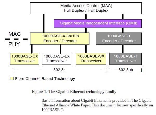
GMII - Gigabit Media-Independent Interface
The gigabit media-independent Interface is an interface between the Media Access Control (MAC) device and the physical layer (PHY). The interface defines speeds up to 1000 Mbit/s, implemented using a data interface clocked at 125 MHz with separate eight-bit data paths for receive and transmit, and is backwards compatible with the media-independent interface (MII) specification. It can also operate on fall-back speeds of 10 or 100 Mbit/s as per the MII specification.
Data on the interface is framed using the IEEE Ethernet standard. As such it consists of a preamble, start frame delimiter, Ethernet headers, protocol specific data and a cyclic redundancy check (CRC).
The GMII interface is defined in IEEE Standard 802.3, 2000 Edition.
SGMII - Serial Gigabit Media-Independent Interface
The serial gigabit media-independent interface is a variant of MII, a standard interface used to connect an Ethernet MAC block to a PHY. It is used for Gigabit Ethernet but can also carry 10/100 Mbit/s Ethernet.
It uses differential pairs at 625 MHz clock frequency DDR for TX and RX data and TX and RX clocks. It differs from GMII by its low-power and low pin-count serial 8b/10b-coded interface (commonly referred to as a SerDes). 10/100 Mbit/s Ethernet is carried by duplicating data words 100/10 times each, so the clock is always at 625 MHz.
QSGMII (Quad Serial Gigabit Media-Independent Interface) is a method of combining four SGMII lines into a 5 Gbit/s interface (625Mhz * 2 = 1.250Ghz?).
XGMII – 10 Gigabit Media-Independent Interface
10 gigabit media-independent interface is a standard defined in IEEE 802.3 for connecting full duplex 10 Gigabit Ethernet (10GbE) ports to each other and to other electronic devices on a printed circuit board. It operates at 156.25 MHz DDR. Typically used for on-chip connections; in chip-to-chip usage [is] mostly replaced by XAUI.
The 10 Gigabit Ethernet standard encompasses a number of different physical layer (PHY) standards. A networking device, such as a switch or a network interface controller may have different PHY types through pluggable PHY modules, such as those based on SFP+ [or XFP]. At the time that the 10 Gigabit Ethernet standard was developed, interest in 10GbE as a wide area network (WAN) transport led to the introduction of a WAN PHY for 10GbE. The WAN PHY encapsulates Ethernet packets in SONET OC-192c frames and operates at a slightly slower data-rate (9.95328 Gbit/s) than the local area network (LAN) PHY.
The WAN PHY uses the same 10GBASE-S, 10GBASE-L and 10GBASE-E optical PMDs as the LAN PHYs and is designated as 10GBASE-SW, 10GBASE-LW or 10GBASE-EW. Its Physical Coding Sublayer 64b/66b PCS is defined in IEEE 802.3 Clause 49 and its Physical Medium Dependent PMDs in Clauses 52. It also uses a WAN Interface Sublayer (WIS) defined in Clause 50 which adds extra encapsulation to format the frame data to be compatible with SONET STS-192c. The WAN PHY was designed to interoperate with OC-192/STM-64 SDH/SONET equipment using a light-weight SDH/SONET frame running at 9.953 Gbit/s.
XAUI
XAUI is a concatenation of the Roman numeral X, meaning ten, and the initials of "Attachment Unit Interface". XAUI is a standard for extending the XGMII (10 Gigabit Media Independent Interface) between the MAC and PHY layer of 10 Gigabit Ethernet (10GbE).
The purpose of the XGMII Extender, which is composed of an XGXS (XGMII Extender Sublayer) at the MAC end, an XGXS at the PHY end and a XAUI between them, is to extend the operational distance of the XGMII and to reduce the number of interface signals. Applications include extending the physical separation possible between MAC and PHY components in a 10 Gigabit Ethernet system distributed across a circuit board.
The implementation of XAUI as an optional XGMII Extender is primarily intended as a chip-to-chip (integrated circuit to integrated circuit) interface implemented with traces on a printed circuit board. Where the XGMII is electrically limited to distances of approximately 7 cm, the XGMII Extender allows distances up to approximately 50 cm.
The XGMII Extender uses 8b/10b encoding. The XGMII is organized into four lanes with each lane conveying a data octet or control character on each edge of the associated clock. The source XGXS converts bytes on an XGMII lane into a self clocked, serial, 8b/10b encoded data stream. Each of the four XGMII lanes is transmitted across one of the four XAUI lanes. Each of the 4 Receive and Transmit lanes operates at a rate of 3.125 Gbit/s.
RXAUI - Reduced 10 Gigabit Attachment Unit Interface
An RXAUI interface uses two 6.25Gbps SerDes lanes operating at 6.25 GHz to carry 10GE, instead of using four 3.125Gbps SERDES lanes. RXAUI is implemented as an Adapter layer (or Mux/Demux layer) between the two 6.25 GHz SerDes lanes (PMA) and the standard IEEE 802.3ae clause 48 XAUI PCS sub-layer. It is introduced as an in-line Mux/Demux layer, which does not require changes in the standard 10 GbE MAC and PCS or any of the inter-layer interfaces defined by IEEE. The Mux/Demux layer does not alter 10-bit symbols. This preserves existing designs created for ASICs, NPUs, and FPGAs. Two of the four XAUI lanes feed one RXAUI lane. On the transmit path each of the two RXAUI adapters folds two XAUI PCS lanes and on the receive path each of the two RXAUI adapters de-muxes the recovered data and splits it back into two XAUI PCS lanes
SerDes - Serializer/Deserializer
A Serializer/Deserializer is a pair of functional blocks commonly used in high speed communications to compensate for limited input/output. These blocks convert data between serial data and parallel interfaces in each direction. The primary use of a SerDes is to provide data transmission over a single/differential line in order to minimize the number of I/O pins and interconnects.
The basic SerDes function is made up of two functional blocks: the Parallel In Serial Out (PISO) block (aka Parallel-to-Serial converter) and the Serial In Parallel Out (SIPO) block (aka Serial-to-Parallel converter).
8b/10b SerDes maps each data byte to a 10bit code before serializing the data. The deserializer uses the reference clock to monitor the recovered clock from the bit stream. The clock information is synthesized into the data bit stream rather than explicitly embedding it.
A common coding scheme used with SerDes is 8b/10b encoding. This supports DC-balance, provides framing, and guarantees frequent transitions. The guaranteed transitions allow a receiver to extract the embedded clock. The control codes allow framing, typically on the start of a packet. The typical 8b/10b SerDes parallel side interfaces have one clock line, one control line and 8 data lines.
Such serializer-plus-8b/10b encoder, and deserializer-plus-decoder blocks are defined in the Gigabit Ethernet specification.
Another common coding scheme used with SerDes is 64b/66b encoding. This scheme statistically delivers DC-balance and transitions through the use of a scrambler. Framing is delivered through the deterministic transitions of the added framing bits.
SFP, SFP+ (SFI) and XFP (XFI) Recap
Physical layer modules for 10GE are not specified in an official standards body but by multi-source agreements (MSAs) that can be negotiated more quickly. Relevant MSAs for 10GbE include XENPAK (and related X2 and XPAK), XFP and SFP+.
The enhanced small form-factor pluggable transceiver, generally called SFP+ is based on the small form-factor pluggable transceiver (SFP) and developed by the ANSI T11 fibre channel group, it is smaller and lower power than XFP. XFP is smaller than XENPACK. SFP+ modules do only optical to electrical conversion, no clock and data recovery, putting a higher burden on the host's channel equalization. SFP+ modules share a common physical form factor with legacy SFP modules, allowing higher port density than XFP and the re-use of existing designs for 24 or 48 ports in a 19" rack width blade.
Optical modules are connected to a host by either a XAUI, XFI or SFI interface. XENPAK, X2, and XPAK modules use XAUI to connect to their hosts. XAUI (XGXS) uses a four-lane data channel and is specified in IEEE 802.3 Clause 48. XFP modules use a XFI interface and SFP+ modules use an SFI interface. XFI and SFI use a single lane data channel and the 64b/66b encoding specified in IEEE 802.3 Clause 49.
SerDes Framer Interface is a standard for telecommunications abbreviated as SFI. Variants include:
- SFI-4 or SerDes Framer Interface Level 4, a standardized Electrical Interface by the Optical Internetworking Forum (OIF) for connecting a synchronous optical networking (SONET) framer component to an optical serializer/deserializer (SerDes) for Optical Carrier transmission rate OC-192 interfaces at about 10 Gigabits per second.
- SFI-5 or SerDes Framer Interface Level 5, a standardized Electrical Interface by the OIF for connecting a SONET Framer component to an optical SerDes for OC-768, about 40 Gbit/s. Electrically, it consists of 16 pairs of SerDes channels each running at 3.125 Gbit/s which gives an aggregate bandwidth of 50 Gbit/s accommodating up to 25% of Forward Error Correction.
The XFI electrical interface specification was a 10 gigabit per second chip-to-chip electrical interface specification defined as part of the XFP multi-source agreement. It was developed by the XFP MSA group.
XFI provides a single lane running at 10.3125 Gbit/s when using a 64B/66B encoding scheme. A serializer/deserializer is often used to convert between XFI and a wider interface such as XAUI that has four lanes running at 3.125 Gbit/s using 8B/10B encoding.
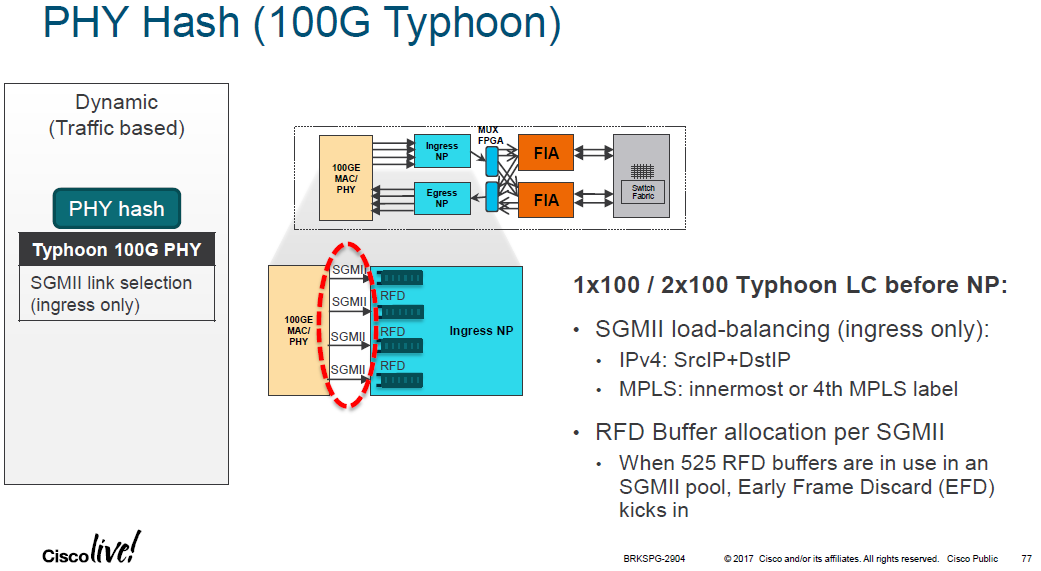
The diagram below shows an example 100GE linecard which is from a Cisco ASR 9000 series router. In this example the Cisco "Typhoon" NPU is being used to process the packets received on a 100GE PHY. The Typhoon NPU can process a maximum of ~45Mpps / 60Gbps full duplex so two NPUs are used, one for Tx and one for Rx. Both NPUs are running in simplex mode so that each one provides a unidirectional throughput of 90Mpps / 120Gbps. However, there are no 100Gbps serial links to connect the all-in-one PHY+MAC controller to the NPU. Instead 4x 25Gbps SGMII links are used. Incoming packets are load-balanced over the 4x SGMII links towards the ingress NPU for ingress traffic processing. For egress traffic process the egress NPU performs the same operation, to load-balance the traffic over 4x 25Gbps SGMII links towards the PHY+MAC controller.
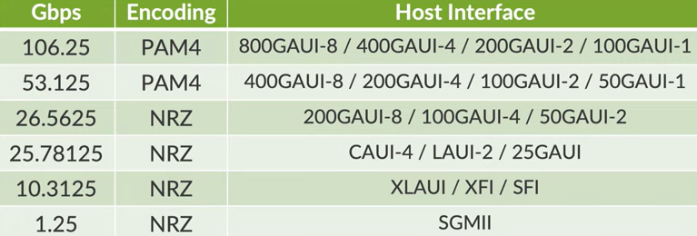
The IEEE 802.3by standard defines a single lane chip-to-chip/chip-to-module interface "25GAUI" which operates at 25.78125 GigaBaud using Non-Return-to-Zero modulation.
The IEEE P802.3cd standard defines the following chip-to-chip/chip-to-module interfaces:
50GAUI-1 single lane FEC encoded electrical interface (26.5625 GigaBaud by one-lane PAM4).
50GAUI-2 dual lane FEC encoded electrical interface (26.5625 GigaBaud by two-lane NRZ).
LAUI-2 dual lane electrical interface (25.78125 GigaBaud by two-lane NRZ).
The 25Gbps MACs tend to drive a 25Gbps PHY which is usually an SFP28 or QSFP28 connector, both of which run a single 28Gbps lane (25Gbps + error correction).
100Gbps interface use can use a variety of connection methods:
- CAUI-10 is a 100 Gbit/s 10-lane electrical interface defined in 802.3ba.
This is used by CFP transceivers. - CAUI-4 is a 100 Gbit/s 4-lane electrical interface defined in 802.3bm Annex 83E with a nominal signaling rate for each lane of 25.78125 GBd using NRZ modulation.
This is used by QSFP28 transceivers. - 100GAUI-1 is a 100 Gbit/s 1-lane electrical interface defined in 802.3ck Annex 120F/G with a nominal signaling rate for each lane of 53.125 GBd using PAM4 modulation and RS-FEC(544,514).
*(Stolen from Nick's YouTube video!)
Previous page: Forwarding Hardware
Next page: Transceivers