Date created: Wednesday, July 25, 2018 3:58:54 PM. Last modified: Wednesday, July 25, 2018 4:45:12 PM
Rosen Draft 7 - Example
Contents:
Topology
Initial Setup
Sending Traffic
Configs (.zip)
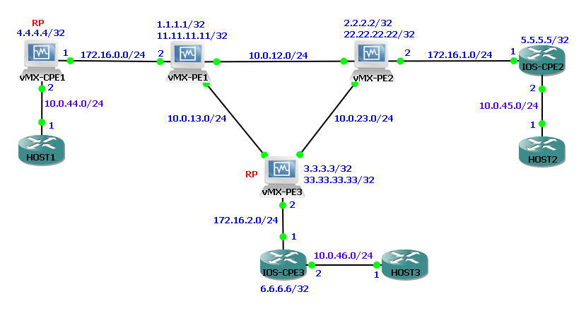
In this topology the three PE routers are running a basic PIM-SM configuration. The VRF "VPN_A" configured on each PE is the customer L3 VPN over which the customer is running multicast. eBGP runs between each PE and attached CPE for IPv4 unicast only, each CPE is advertising it's loopback0 IP into the L3 VPN. PIM is configured on the PE-CE link inside the VRF.
A unique /24 PIM-SSM group address range has been assigned for this L3 VPN on each PE under the customer's VRF. Between PEs the address family inet-mdt is enabled so that BGP signalled autodiscovery for data MDTs can occur.
A draft-rosen MVPN with service provider tunnels operating in SSM mode uses BGP signalling for autodiscovery of the PE routers. These MVPNs are also referred to as Draft Rosen 7. Each PE sends an MDT-SAFI (AFI=1, SAFI=66) BGP NLRI which contains the following information:
- Route distinguisher
- Unicast address of the PE router to which the source site is attached (usually the loopback)
- Multicast group address
- Route target extended community attribute
Each remote PE router imports the MDT-SAFI advertisements from each of the other PE routers if the route target matches.
Each PE router then joins the (S,G) tree rooted at each of the other PE routers. After the PE routers are discovered, PIM is notified of the multicast source and group addresses. PIM binds the (S,G) state to the multicast tunnel (mt) interface and sends a join message for that group.
The output below shows all PEs have exchanged BGP routes for the default 232.1.1.1 RP-discovery group, because they have matching RTs they are imported into the customers multicast VRF:
lab@vMX-PE1> show route table bgp.mdt.0

bgp.mdt.0: 2 destinations, 2 routes (2 active, 0 holddown, 0 hidden)
+ = Active Route, - = Last Active, * = Both

1:100:1:2.2.2.2:232.1.1.1/144
                   *[BGP/170] 00:07:49, localpref 100, from 2.2.2.2
                      AS path: I, validation-state: unverified
                    > to 10.0.12.2 via ge-0/0/3.0
1:100:1:3.3.3.3:232.1.1.1/144
                   *[BGP/170] 02:09:56, localpref 100, from 3.3.3.3
                      AS path: I, validation-state: unverified
                    > to 10.0.13.3 via ge-0/0/4.0

VPN_A.mdt.0: 3 destinations, 3 routes (3 active, 0 holddown, 0 hidden)
+ = Active Route, - = Last Active, * = Both

1:100:1:1.1.1.1:232.1.1.1/144
                   *[MVPN/70] 07:23:31, metric2 1
                      Indirect
1:100:1:2.2.2.2:232.1.1.1/144
                   *[BGP/170] 07:17:17, localpref 100, from 2.2.2.2
                      AS path: I, validation-state: unverified
                    > to 10.0.12.2 via ge-0/0/3.0
1:100:1:3.3.3.3:232.1.1.1/144
                   *[BGP/170] 06:38:38, localpref 100, from 3.3.3.3
                      AS path: I, validation-state: unverified
                    > to 10.0.13.3 via ge-0/0/4.0
Below the PIM output shows that inside the global routing table each PE has joined the multicast groups signalled by the other PEs over BGP-MDT. There are three source specific multicast groups (S,G) 232.1.1.1,1.1.1.1, 232.1.1.1,2.2.2.2 and 232.1.1.1,3.3.3.3. They were signalled by BGP. The output below is from vMX-PE1 which is why the upstream interface list is "local" as this PE is the root of this source-specific multicast group tree and the downstream interface list contains the interfaces facing vMX-PE2 and vMX-PE3.
vMX-PE1 is also downstream of the 232.1.1.1,2.2.2.2 and 232.1.1.1,3.3.3.3 groups so in both cases the upstream interface list contains the point-to-point interface towards the relevant PE and the downstream interface (how this PE would receive traffic from those upstream nodes) is via the point-to-multipoint GRE tunnel interface mt-0/0/10.1081344:
lab@vMX-PE1> show pim join inet detail
Instance: PIM.master Family: INET
R = Rendezvous Point Tree, S = Sparse, W = Wildcard

Group: 232.1.1.1
    Source: 1.1.1.1
    Flags: sparse,spt
    Upstream interface: Local
    Downstream neighbors:
        Interface: ge-0/0/3.0
        Interface: ge-0/0/4.0

Group: 232.1.1.1
    Source: 2.2.2.2
    Flags: sparse,spt
    Upstream interface: ge-0/0/3.0
    Downstream neighbors:
        Interface: mt-0/0/10.1081344

Group: 232.1.1.1
    Source: 3.3.3.3
    Flags: sparse,spt
    Upstream interface: ge-0/0/4.0
    Downstream neighbors:
        Interface: mt-0/0/10.1081344
Each PE has discovered its PIM neighbours through multicast hellos, below vMX-PE1 has two PIM neighbours (vMX-PE2 and vMX-PE3) inside the global routing table / inet.0 however, the available groups to join (shown in the about above) were signalled by BGP-MDT:
lab@vMX-PE1> show pim neighbors
B = Bidirectional Capable, G = Generation Identifier
H = Hello Option Holdtime, L = Hello Option LAN Prune Delay,
P = Hello Option DR Priority, T = Tracking Bit

Instance: PIM.master
Interface           IP V Mode        Option       Uptime Neighbor addr
ge-0/0/3.0           4 2             HPLGT      00:14:27 10.0.12.2
ge-0/0/4.0           4 2             HPLGT      00:14:27 10.0.13.3


lab@vMX-PE1> show pim mdt instance VPN_A
Instance: PIM.VPN_A
Tunnel direction: Outgoing
Tunnel mode: PIM-SSM
Default group address: 232.1.1.1
Default source address: 1.1.1.1
Default tunnel interface: mt-0/0/10.32768
Default tunnel source: 0.0.0.0

Instance: PIM.VPN_A
Tunnel direction: Incoming
Tunnel mode: PIM-SSM
Default group address: 232.1.1.1
Default source address: 2.2.2.2
Default tunnel interface: mt-0/0/10.1081344
Default tunnel source: 0.0.0.0

Instance: PIM.VPN_A
Tunnel direction: Incoming
Tunnel mode: PIM-SSM
Default group address: 232.1.1.1
Default source address: 3.3.3.3
Default tunnel interface: mt-0/0/10.1081344
Default tunnel source: 0.0.0.0
vMX-PE1 also has a PIM adjacency with vMX-CPE1 inside the VRF VPN_A and with lo0.1 on vMX-PE2 and vMX-PE3:
lab@vMX-PE1> show pim neighbors instance VPN_A
B = Bidirectional Capable, G = Generation Identifier
H = Hello Option Holdtime, L = Hello Option LAN Prune Delay,
P = Hello Option DR Priority, T = Tracking Bit

Instance: PIM.VPN_A
Interface           IP V Mode        Option       Uptime Neighbor addr
ge-0/0/5.0           4 2             HPLGT      00:23:04 172.16.0.1
mt-0/0/10.32768      4 2             HPLGT      02:19:21 22.22.22.22
mt-0/0/10.32768      4 2             HPLGT      02:00:16 33.33.33.33
mt-0/0/10.32768 is the point to multipoint tunnel inside the VPN_A VRF.
mt-0/0/10.1081344 is the point to multipoint tunnel inside inet0 / GRT.
Within the inet.0 table vMX-PE3 is statically configured as the rendezvous point, within the VRF vMX-CE1 is statically configured as the RP. SSM is being used so the RP is not actually being used to find an available source like with ASM (Any Source Multicast):
lab@vMX-PE1> show pim rps inet
Instance: PIM.master

address-family INET
RP address      Type        Mode   Holdtime Timeout Groups Group prefixes
3.3.3.3         static      sparse        0    None      0 224.0.0.0/4

lab@vMX-PE1> show pim rps inet instance VPN_A
Instance: PIM.VPN_A

address-family INET
RP address      Type        Mode   Holdtime Timeout Groups Group prefixes
4.4.4.4         static      sparse        0    None      1 224.0.0.0/4
The output below shows just a default any-source multicast group of (*,G) *,224.0.1.40 initially exists inside the multicast VRF VPN_A. 224.0.1.40 is the IANA well know group address for rp-discovery. vMX-CE1 is statically configured as the RP inside this VRF on all devices which is why the vMX-PE1 to vMX-CE1 interface is listed as the upstream interface for this default group and the point-to-multipoint GRE interface towards vMX-PE2 and vMX-PE3 inside the VRF is listed as the downstream interface:
lab@vMX-PE1> show pim join inet detail instance VPN_A
Instance: PIM.VPN_A Family: INET
R = Rendezvous Point Tree, S = Sparse, W = Wildcard

Group: 224.0.1.40
    Source: *
    RP: 4.4.4.4
    Flags: sparse,rptree,wildcard
    Upstream interface: ge-0/0/5.0
    Downstream neighbors:
        Interface: mt-0/0/10.32768
Equally, on vMX-PE2 we can see that the upstream interface is the point to multipoint tunnel towards vMX-PE1 and vMX-PE3 and the downstream interface is ge-0/0/5 facing IOS-CPE2. So everything looks to be in place however the RP isn’t used in SSM:
lab@vMX-PE2> show pim join inet detail instance VPN_A
Instance: PIM.VPN_A Family: INET
R = Rendezvous Point Tree, S = Sparse, W = Wildcard

Group: 224.0.1.40
    Source: *
    RP: 4.4.4.4
    Flags: sparse,rptree,wildcard
    Upstream interface: mt-0/0/10.32768
    Downstream neighbors:
        Interface: ge-0/0/5.0
Below is the output from vMX-CE1 showing it has a PIM a neighborship with vMX-PE1 and the only group currently is the default RP-announce group, the downstream interface for this is ge-0/0/3 facing vMX-PE1, the upstream interface is Local this device is the static RP:
lab@vMX-CPE1> show pim neighbors instance VPN_A
B = Bidirectional Capable, G = Generation Identifier
H = Hello Option Holdtime, L = Hello Option LAN Prune Delay,
P = Hello Option DR Priority, T = Tracking Bit

Instance: PIM.VPN_A
Interface           IP V Mode        Option       Uptime Neighbor addr
ge-0/0/3.0           4 2             HPLGT      01:01:57 172.16.0.2

lab@vMX-CPE1> show pim join instance VPN_A inet detail
Instance: PIM.VPN_A Family: INET
R = Rendezvous Point Tree, S = Sparse, W = Wildcard

Group: 224.0.1.40
    Source: *
    RP: 4.4.4.4
    Flags: sparse,rptree,wildcard
    Upstream interface: Local
    Downstream neighbors:
        Interface: ge-0/0/3.0
A ping is started on HOST1 towards 232.10.10.2 from it's source IP 10.0.44.1. vMX-CE1 recognises the packet destination is within the 232/8 source specific multicast ranges and creates a new PIM group entry, a source specific entry (S,G) 10.0.44.1,232.1.1.1. Initially there are no downstream interfaces for this S,G entry as no listeners have joined this SSM group, only an upstream interface ge-0/0/4 towards HOST1 interface Fa0/0:
lab@vMX-CPE1> show pim join instance VPN_A inet detail
Instance: PIM.VPN_A Family: INET
R = Rendezvous Point Tree, S = Sparse, W = Wildcard

Group: 224.0.1.40
    Source: *
    RP: 4.4.4.4
    Flags: sparse,rptree,wildcard
    Upstream interface: Local
    Downstream neighbors:
        Interface: ge-0/0/3.0

Group: 232.1.1.1
    Source: 10.0.44.1
    Flags: sparse,spt
    Upstream interface: ge-0/0/4.0
    Downstream neighbors:
Next a source specific IGMP Join is simulated on HOST3 interface Fa0/0, this will be a listener for this source specific group 232.10.10.1,10.0.44.1:
conf t
 int Fa0/0
  ip igmp join-group 232.10.10.1 source 10.0.44.1
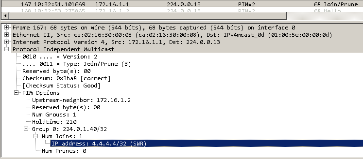
IOS-CPE2 receives the IGMP join request. IOS-CPE2 is pre-preconfigured with the static RP for this customer VRF, 4.4.4.4, the loopback IP on vMX-CPE1. IOS-CPE2 first sends a PIM Join request towards vMX-PE2 to the IANA well-known All PIM Routers address 224.0.013, to join the IANA well-known RP discovery group address 224.0.1.40 to register with the RP 4.4.4.4 (vMX-CPE1 Loopback):
IOS-CPE2 also automatically sets up a GRE tunnel called Tu0 towards the RP for the VRF, 4.4.4.4:
*Jul  4 15:00:14.762: %LINEPROTO-5-UPDOWN: Line protocol on Interface Tunnel0, changed state to up
IOS-CPE2#show int desc | inc Tu0
Tu0                            up             up       Pim Register Tunnel (Encap) for RP 4.4.4.4 on VRF VPN_A

IOS-CPE2#show derived-config interface Tu0
Building configuration...

Derived configuration : 226 bytes
!
interface Tunnel0
 description Pim Register Tunnel (Encap) for RP 4.4.4.4 on VRF VPN_A
 ip unnumbered Loopback0
 tunnel source Loopback0
 tunnel destination 4.4.4.4
 tunnel tos 192
 tunnel vrf VPN_A
 no routing dynamic
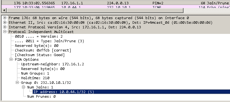
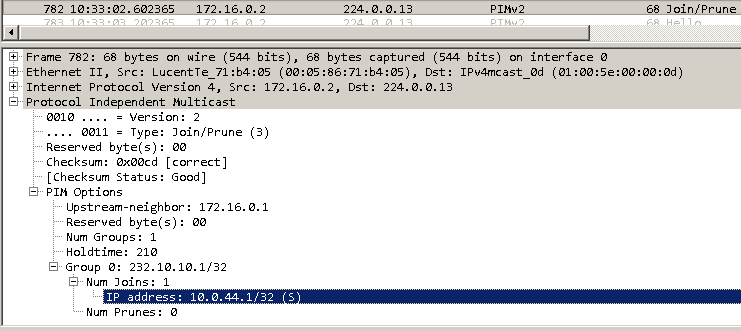
IOS-CPE2 also converts the IGMP Join it received from HOST2 into a PIM Join and sends this towards vMX-PE2. The screenshot below shows that IOS-CPE2 sends a PIM Join to the IANA well-known address for All PIM Routers, 224.0.0.13. The PIM Join is for the group 232.10.10.1 with the specific source of 10.0.44.1. The upstream neighbour is the vMX-PE2 interface IP on the vMX-PE2 to IOS-CPE2 link, vMX-PE2 is upstream of IOS-CPE2 in this multicast tree towards the RP:
IOS-CPE2 now has the following multicast routes present within the customer VRF, one source specific S,G route to receive traffic sent from HOST1 and forward it to HOST2 with vMX-PE2 as the RP, and one any source *,G route for the IANA well-known rp-discovery group address:
IOS-CPE2#show ip mroute  vrf VPN_A
…
(10.0.44.1, 232.10.10.1), 02:08:16/00:02:34, flags: sTI
  Incoming interface: FastEthernet0/0, RPF nbr 172.16.1.2
  Outgoing interface list:
    FastEthernet0/1, Forward/Sparse, 02:08:16/00:02:34

(*, 224.0.1.40), 04:22:35/00:02:32, RP 4.4.4.4, flags: SJCL
  Incoming interface: FastEthernet0/0, RPF nbr 172.16.1.2
  Outgoing interface list:
    Loopback0, Forward/Sparse, 04:22:34/00:02:32
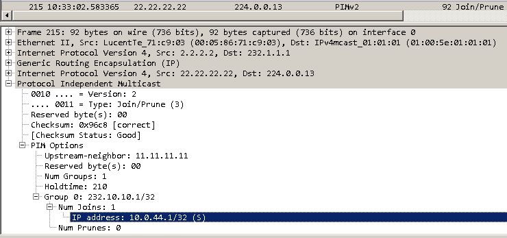
vMX-PE2 receives the PIM Join message on an interface inside a VRF, “VPN_A” in this case. vMX-PE2 will multicast the PIM Join to the group address setup that reaches the other PEs in the core, 232.1.1.1, from its loopback IP 2.2.2.2. The packet is sent over the inet.1 point to multipoint GRE tunnel from vMX-PE2 to vMX-PE1 and vMX-PE3. This is because BGP has signalled 232.1.1.1 from each PE to every other PE:
lab@vMX-PE2> show route table inet.1 | find 232.1.1.1
232.1.1.1,1.1.1.1/64*[PIM/105] 02:34:54
                      Multicast (IPv4) Composite
232.1.1.1,2.2.2.2/64*[PIM/105] 02:35:26
                      Multicast (IPv4) Composite
232.1.1.1,3.3.3.3/64*[PIM/105] 01:56:10
                      Multicast (IPv4) Composite
Inside the layer of multicast GRE headers is the PIM Join request. vMX-PE2 has set the upstream neighbour to be 11.11.11.11, vMX-PE1s loopback IP inside the VRF:
vMX-PE2 adds the vMX-PE2 to IOS-CPE2 link ge-0/0/5 to the downstream interface list for this SSM S,G group:
lab@vMX-PE2> show pim join inet detail instance VPN_A
Instance: PIM.VPN_A Family: INET
R = Rendezvous Point Tree, S = Sparse, W = Wildcard

Group: 224.0.1.40
    Source: *
    RP: 4.4.4.4
    Flags: sparse,rptree,wildcard
    Upstream interface: mt-0/0/10.32768
    Downstream neighbors:
        Interface: ge-0/0/5.0

Group: 232.10.10.1
    Source: 10.0.44.1
    Flags: sparse,spt
    Upstream interface: mt-0/0/10.32768
    Downstream neighbors:
        Interface: ge-0/0/5.0
vMX-PE2 also adds a multicast route inside the customer VRF for this S,G, the next hop interface index resolves to the vMX-PE2 to IOS-CPE2 interface ge-0/0/5, packets heading to 232.10.10.1 from 10.0.44.1 will be sent out of this interface. This shows how the PIM information above is implemented in to the RIB and eventually FIB:
lab@vMX-PE2> show route table VPN_A.inet.1 232.10.10.1/32 detail

VPN_A.inet.1: 6 destinations, 6 routes (6 active, 0 holddown, 0 hidden)
232.10.10.1, 10.0.44.1/64 (1 entry, 1 announced)
        *PIM    Preference: 105
                Next hop type: Multicast (IPv4) Composite, Next hop index: 1048579
                Address: 0x973011c
                Next-hop reference count: 4
                State: <Active Int Ext>
                Age: 12
                Validation State: unverified
                Task: PIM.VPN_A
                Announcement bits (1): 0-KRT
                AS path: I

lab@vMX-PE2> show route forwarding-table | find 232.10.10.1
232.10.10.1.10.0.44.1/64
                   user     0                    indr  1048579     3
                                                 comp      612     1

lab@vMX-PE2> start shell user root
Password:
root@vMX-PE2% vty fpc0


BSD platform (Pentium processor, 512MB memory, 0KB flash)

VMX(vMX-PE2 vty)# show nhdb id 1048579 recursive
1048579(Indirect, IPv4, ifl:0:-, pfe-id:0, i-ifl:0:-)
    612(Compst, IPv4, ifl:0:-, pfe-id:0, comp-fn:multicast)
        1048577(Unicast, IPv4, ifl:335:ge-0/0/5.0, pfe-id:0)
The PIM Join is received by vMX-PE1 and the group entry has been created on vMX-PE1 with the downstream interface set to the point-to-multipoint GRE tunnel towards vMX-PE2 and vMX-PE3, and the upstream interface set to the vMX-PE1 to vMX-CE1 link ge-0/0/5:
lab@vMX-PE1> show pim join inet detail instance VPN_A
Instance: PIM.VPN_A Family: INET
R = Rendezvous Point Tree, S = Sparse, W = Wildcard

Group: 224.0.1.40
    Source: *
    RP: 4.4.4.4
    Flags: sparse,rptree,wildcard
    Upstream interface: ge-0/0/5.0
    Downstream neighbors:
        Interface: mt-0/0/10.32768

Group: 232.10.10.1
    Source: 10.0.44.1
    Flags: sparse,spt
    Upstream interface: ge-0/0/5.0
    Downstream neighbors:
        Interface: mt-0/0/10.32768
vMX-PE1 forwards the PIM Join request on to vMX-CPE1. The upstream neighbour is vMX-CPE1 link IP address:
Finally vMX-CPE1 has updated the downstream interface list to include its link towards vMX-PE1 ge-0/0/4:
lab@vMX-CPE1> show pim join inet detail instance VPN_A
Instance: PIM.VPN_A Family: INET
R = Rendezvous Point Tree, S = Sparse, W = Wildcard

Group: 224.0.1.40
    Source: *
    RP: 4.4.4.4
    Flags: sparse,rptree,wildcard
    Upstream interface: Local
    Downstream neighbors:
        Interface: ge-0/0/3.0

Group: 232.10.10.1
    Source: 10.0.44.1
    Flags: sparse,spt
    Upstream interface: ge-0/0/4.0
    Downstream neighbors:
        Interface: ge-0/0/3.0
At this point HOST1 is getting responses to its ping messages:
HOST1#ping 232.10.10.1 source 10.0.44.1 repeat 1000
Type escape sequence to abort.
Sending 1000, 100-byte ICMP Echos to 232.10.10.1, timeout is 2 seconds:
Packet sent with a source address of 10.0.44.1

Reply to request 0 from 10.0.45.1, 40 ms
Reply to request 1 from 10.0.45.1, 8 ms
Reply to request 2 from 10.0.45.1, 36 ms
Reply to request 3 from 10.0.45.1, 32 ms
The same IGMP Join can be configured on HOST3 to make it listener for the same S,G range. The same process happenes, a Join ripples from IOS-CPE3 to vMX-CPE1 with the outgoing interfaces along the path added to the PIM Group details. Now HOST1 receives two ICMP echo replies for ever echo request sent, one from HOST2 and one from HOST3:
HOST1#ping 232.10.10.1 source 10.0.44.1 repeat 1000
Type escape sequence to abort.
Sending 1000, 100-byte ICMP Echos to 232.10.10.1, timeout is 2 seconds:
Packet sent with a source address of 10.0.44.1

Reply to request 0 from 10.0.45.1, 48 ms
Reply to request 0 from 10.0.46.1, 52 ms
Reply to request 1 from 10.0.45.1, 24 ms
Reply to request 1 from 10.0.46.1, 56 ms
Reply to request 2 from 10.0.45.1, 8 ms
Reply to request 2 from 10.0.46.1, 36 ms
Reply to request 3 from 10.0.45.1, 32 ms
Reply to request 3 from 10.0.46.1, 56 ms
Reply to request 4 from 10.0.46.1, 16 ms
Reply to request 4 from 10.0.45.1, 40 ms
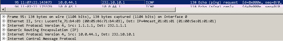
It can be seen in the packet capture above on the link between vMX-PE1 and vMX-PE2, that the ICMP echo requests are sent to the multicast address 232.1.1.1 inside the VRF. vMX-PE1 sends the data over the point-to-multipoint GRE tunnel towards vMX-PE2 and vMX-PE3 also with the destination address of 232.1.1.1. Both vMX-PE1 and vMX-PE2 receive the ICMP echo requests but only vMX-PE1 has a receiver active for this SSM group at present.
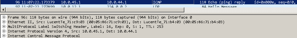
ICMP echo replies are “normal” unicast responses back to the source IP 10.0.45.2:
Below the multicast routes can be seen from vMX-PE2’s perspective inside the customers multicast VRF:
lab@vMX-PE2> show route table VPN_A.mdt.0

VPN_A.mdt.0: 3 destinations, 3 routes (3 active, 0 holddown, 0 hidden)
+ = Active Route, - = Last Active, * = Both

1:100:1:1.1.1.1:232.1.1.1/144
                   *[BGP/170] 05:43:07, localpref 100, from 1.1.1.1
                      AS path: I, validation-state: unverified
                    > to 10.0.12.1 via ge-0/0/3.0
1:100:1:2.2.2.2:232.1.1.1/144
                   *[MVPN/70] 06:00:47, metric2 1
                      Indirect
1:100:1:3.3.3.3:232.1.1.1/144
                   *[BGP/170] 01:06:39, localpref 100, from 3.3.3.3
                      AS path: I, validation-state: unverified
                    > to 10.0.23.3 via ge-0/0/4.0

lab@vMX-PE2> show route table VPN_A.inet.1

VPN_A.inet.1: 4 destinations, 4 routes (4 active, 0 holddown, 0 hidden)
+ = Active Route, - = Last Active, * = Both

224.0.0.0/4        *[Multicast/180] 06:00:40
                      MultiResolve
224.0.0.0/24       *[Multicast/180] 06:00:40
                      MultiDiscard
232.0.0.0/8        *[Multicast/180] 06:00:40
                      MultiResolve
232.1.1.1,10.0.44.1/64*[PIM/105] 00:36:38
                      Multicast (IPv4) Composite
On vMX-PE1 we can see that the point-to-multipoint GRE tunnel mt-0/0/10.32768 is the outgoing interface for traffic to this multicast group (even when HOST3 joins the multicast group as a 2nd listener the output below stays the same):
lab@vMX-PE1> show route table VPN_A.inet.1 detail | find "225.1.1.1"
225.1.1.1, 10.0.44.1/64 (1 entry, 1 announced)
        *PIM    Preference: 105
                Next hop type: Multicast (IPv4) Composite, Next hop index: 1048578
                Address: 0x97301a8
                Next-hop reference count: 2
                State: <Active Int Ext>
                Age: 14:26
                Validation State: unverified
                Task: PIM.VPN_A
                Announcement bits (1): 0-KRT
                AS path: I

lab@vMX-PE1> start shell user root
Password:
root@vMX-PE1% vty fpc0


BSD platform (Pentium processor, 512MB memory, 0KB flash)

VMX(vMX-PE1 vty)# show nhdb id 1048578 recursive
1048578(Indirect, IPv4, ifl:0:-, pfe-id:0, i-ifl:0:-)
    617(Compst, IPv4, ifl:0:-, pfe-id:0, comp-fn:multicast)
        616(Unicast, IPv4, ifl:336:mt-0/0/10.32768, pfe-id:0)
After adding the relevant IGMP Join statements, all HOSTs are senders and receivers for all others (this is not practical in real deployments but fun for testing):
interface FastEthernet0/0
 ip igmp join-group 232.30.30.1 source 10.0.46.1
 ip igmp join-group 232.20.20.1 source 10.0.45.1

HOST1#ping 232.10.10.1 source 10.0.44.1
Type escape sequence to abort.
Sending 1, 100-byte ICMP Echos to 232.10.10.1, timeout is 2 seconds:
Packet sent with a source address of 10.0.44.1

Reply to request 0 from 10.0.45.1, 28 ms
Reply to request 0 from 10.0.46.1, 32 ms


interface FastEthernet0/0
 ip igmp join-group 232.30.30.1 source 10.0.46.1
 ip igmp join-group 232.10.10.1 source 10.0.44.1

HOST2#ping 232.20.20.1 source 10.0.45.1
Type escape sequence to abort.
Sending 1, 100-byte ICMP Echos to 232.20.20.1, timeout is 2 seconds:
Packet sent with a source address of 10.0.45.1

Reply to request 0 from 10.0.44.1, 60 ms
Reply to request 0 from 10.0.46.1, 64 ms


interface FastEthernet0/0
 ip igmp join-group 232.20.20.1 source 10.0.45.1
 ip igmp join-group 232.10.10.1 source 10.0.44.1

HOST3#ping 232.30.30.1 source 10.0.46.1
Type escape sequence to abort.
Sending 1, 100-byte ICMP Echos to 232.30.30.1, timeout is 2 seconds:
Packet sent with a source address of 10.0.46.1

Reply to request 0 from 10.0.44.1, 20 ms
Reply to request 0 from 10.0.45.1, 56 ms
Previous page: Explicit Path Interop (IOS-XR and Junos)
Next page: Rosen Draft 7 - Overview