Date created: Friday, June 24, 2016 7:06:36 PM. Last modified: Tuesday, January 22, 2019 10:42:00 AM
ASR9000 QoS and LAG QoS
References:
https://supportforums.cisco.com/document/135651/asr9000xr-feature-order-operation
http://www.cisco.com/c/en/us/td/docs/routers/asr9000/hardware/overview/guide/asr9kOVRGbk/asr9kOVRGfuncdescription.html
BRKSPG-2904 - ASR-9000/IOS-XR hardware Architecture, QOS, EVC, IOS-XR Configuration and Troubleshooting
https://supportforums.cisco.com/document/12135016/asr9000xr-understanding-and-troubleshooting-fabric-issues-a9k
http://www.cisco.com/c/en/us/td/docs/routers/asr9000/software/asr9k_r6-0/general/release/notes/reln-601a9k.html#concept_D31CCC2886D343A499A6D458B9980E97
https://supportforums.cisco.com/document/105496/asr9000xr-understanding-route-scale#Using_the_ASR9000_as_a_Route_Reflector
https://www.cisco.com/c/en/us/td/docs/routers/asr9000/software/asr9k_r5-3/qos/configuration/guide/b_qos_cg53xasr9k/b_qos_cg53xasr9k_chapter_0100.html
https://www.cisco.com/c/en/us/td/docs/routers/asr9000/software/asr9k_r5-3/qos/configuration/guide/b_qos_cg53xasr9k/b_qos_cg53xasr9k_chapter_0101.html
https://www.cisco.com/c/en/us/td/docs/routers/asr9000/software/asr9k_r5-3/qos/configuration/guide/b_qos_cg53xasr9k/b_qos_cg53xasr9k_chapter_0110.html
https://supportforums.cisco.com/t5/service-providers-documents/asr9000-xr-understanding-qos-default-marking-behavior-and/ta-p/3128709
Contents:
QoS Order-of-Operations
Ingress QoS Order-of-Operations
Egress QoS Order-of-Operations
Hardware Queues
Policers
Shapers
Policer and Shaper Accounting
WRED and Queue Limits
Guaranteed and Remaining Bandwidths
Port Level Shaping
VoQs and Implicit Trust
Default QoS Behaviour
LAG/Bundle QoS
Hardware Specifications
Debugging Commands
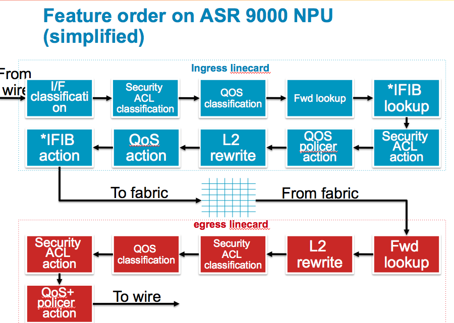
Ingress QoS Order-of-Operations:
I/F Classification
Ingress packets are checked against the TCAM to see what (sub)interface it belongs to. Once known the router can derive the uIDB (micro IDB, Interface Descriptor Block) and know which features need to be applied to the ingressing packet.
ACL Classification
If there is an ACL applied to the interface, a set of keys are built and sent over to the TCAM to find out if this packet is a permit or deny on that configured ACL. Only the result is received, no action is taken yet. In the case of SPAN this is where the "capture" ACE keyword is matched too.
QOS Classification
If there is a QoS policy applied the TCAM is queried with the set of keys to find out if a particular class-map is being matched. The return result is effectively an identifier to the class of the policy-map, so we know what functionality to apply on this packet when QoS actions are executed.
ACL and QoS Classification Notes:
Enabling either ACLs or QoS will result in a TCAM lookup for a match. An ACL lookup takes X time, a QoS lookup takes Y time, enabling both ACL and QoS will not give you an X+Y PPS degradation because the TCAM lookup for them both is done in parallel. BGP flowspec, Open flow and CLI Based PBR use PBR lookup, which logically happens between ACL and QoS.
Forwarding lookup
The ingress forwarding lookup does not traverse the whole forwarding tree yet, it only tries to find the egress interface and thus the egress line card. When bundles are used and members are spread over different linecards the router needs to compute the hash to identify the egress line card for the egress member port.
Note: If uRPF is enabled a full ingress FIB lookup (same as the egress) is performed, this is intense and therefore uRPF can have a relatively larger impact on the PPS.
IFIB Lookup
The iFIB checks which internal packet processor the ingressing packet should be forwarded to. For example ARP and NetFlow are handled by the LC NPU but BGP and OSPF are handled by the RSP. In the case of NetFlow and packets are dropped by an ACL or QoS policer, the flow record will be sampled/exported so this information is captured but a flag is set to indicate the packet was dropped.
ACL Action
If the packet is subject to an ACL deny the packet is dropped now.
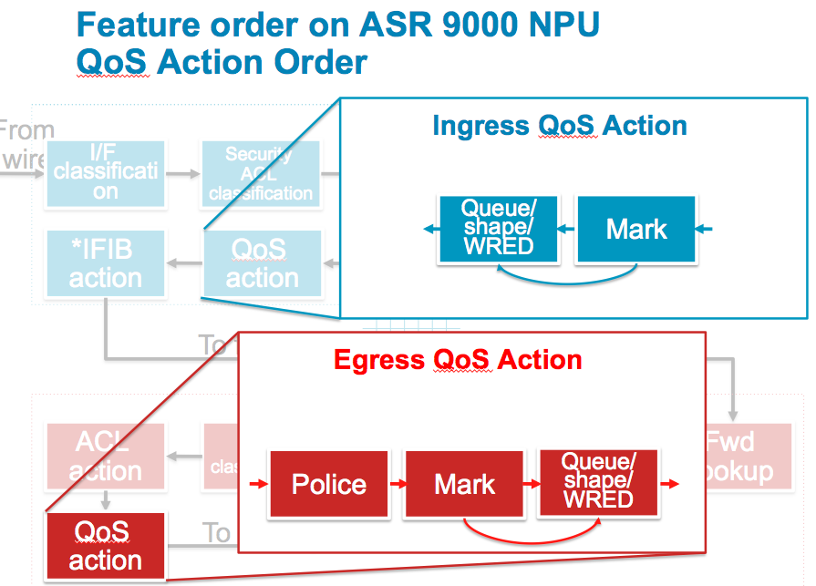
QOS Action
Any policer action is done during this stage as well as marking. QoS shaping and buffering is done by the traffic manager which is a separate stage in the NPU.
Note on ACL and QoS Action
Since the LC NPUs use TOPs (task optimized processors) in the common design of four linear TOPs to create a packet pipeline (a parse TOP, feeds into the search TOP, feeds into the resolve TOP and finally feeds into the modify TOP) ACL and QoS actions are applied here even though the ACL and QoS classification sections earlier.
PERSONAL SPECULATION: The reason the order of operations is ACL & QoS classification, forwarding lookup, iFIB lookup then finally ACL and QoS action, meaning that dropped packets by an ACL deny statement for example, which could seemingly have been dropped earlier in the process; is because all these steps are covered by the packets going through the TOPs pipeline and only the modify TOP (the final one) drops packets, which is why ACL and QoS actions happen after an iFIB and egress LC/NPU lookup.
More info on TOPs here: /index.php?page=forwarding-hardware#tops
L2 rewrite
During the L2 rewrite in the ingress stage the LC is applying the fabric header (super frame). In the case of an MPLS labelled packet which requires a SWAP operation, the SWAP is performed in the ingress pipeline before the packet is forwarded to the switch fabric. The egress MAC address (in the example of routing from a layer 3 ingress port to a layer 3 egress port) is looked up in the egress linecard, this improves the scaling limits of the line cards by not having to know all possible egress adjacency rewrite information.
QOS Action
Any other QoS actions are made now. Marking is performed first then and queuing, shaping and WRED are executed. This means that any mutations or re-markings are acted upon by WRED. Note that packets that were previously policed or dropped by ACL are not seen in this stage anymore. It is important to understand that dropped packets are removed from the pipeline, so when there are counter discrepancies, they may have been processed/dropped by an earlier feature.
iFIB action
Either the packet is forwarded over the fabric or handed over to the LC CPU here. If the packet is destined for the RSP CPU, it is forwarded over the fabric to the RSP destination (the RSP is a line card from a fabric point of view, the RSP requests fabric access to inject packets in the same fashion an LC would).
General
The ingress linecard will also do the TTL decrement on the packet and if the TTL exceeds the packet is punted to the LC CPU for an ICMP TTL exceed message. The number of packets we can punt is subject to LPTS policing.
Egress QoS Order-of-Operations:
Forwarding lookup
The egress line card performs a full FIB lookup down the leaf to get the rewrite string. This full FIB lookup will provide everything for the packet routing, such as egress interface, encapsulation, and adjacency information.
L2 rewrite
With the information received from the forwarding lookup the router can rewrite the packet headers applying Ethernet headers, VLANs, MPLS labels etc.
Security ACL classification
During the FIB lookup the egress interface has been determined and which features are applied. As with the ingress the keys can be built to query the TCAM for an ACL result based on the application to the egress interface.
QOS Classification
As with the ingress process, the TCAM is queried to identify the QoS class-map and matching criteria for this packet on an egress QoS policy.
ACL action
Any ACL action is executed now.
QOS action
Any QoS action is executed now. Any policing is performed, then marking and then queuing, shaping and WRED. This means packets that are re-marked will be subject to WRED based on their re-marked values. Note that packets dropped by a policer are not seen in the remainder of this stage.
General
MTU verification is only done on the egress line card to determine if fragmentation is needed. The egress line card will punt the packet to the LC CPU of the egress line card if fragmentation is requirement. Fragmentation is done in software and no features are applied on these packets on the egress line card. The number of packets that can be punted for fragmentation is NPU bound and limited by LPTS.
More info can be found here. When packets enter the Typhoon NPU the ICU (Internal Classification Unit) can pre-parse the packets and classify them into one of 64 ICFDQs (Input Classification Frame Descriptor Queues). Each ICFDQ has 4 CoS queues. Network control traffic is CoS >= 6, high priority traffic is CoS = 5, low priority traffic is CoS < 5, the fourth queue is unused.
Inside the ICFDQs, EFD (Early Fast Discard) is a mechanism which looks at the queue before the packets enter the [TOPs] pipeline of the NPU. The EFD was software based with the ICU in Typhoon cards and has become hardware based with the ICU in Tomahawk cards.
The EFD can perform some minimalistic checking on precedence, EXP or CoS values to determine if a low or high priority packet is being processed. If the pipeline is clogged it can drop some lower priority packets to save the higher priority ones before they enter the pipeline by using Strict-priority Round-Robin.
When packets leave the TOPs pipeline there is an egress Traffic Manager ASIC on Typhoon NPUs (two egress TMs per Tomahawk NPU) which feeds the Fabric Interconnect ASIC. The FIA has 4 VoQs per VIQ, two are strict priority queues, one is for best effort traffic and the last is unused. When packets arrive from the switch fabric at the egress FIA, the FIA has the same group of four class queues for each NPU it serves and again only three of the queues in each group are used.
When defining policers at high(er) rates make sure the committed burst and excess burst are set correctly.
The formula to follow is for 1.5 seconds of burst (the Cisco recommend):
Set Bc to CIR bps * (1 byte) / (8 bits) * 1.5 seconds
and
Be=2xBc
1.5 seconds is quite high for some hardware buffer sizes. 250ms of burst (for comparison) would be:
(CIR Bps / 8) *0.25.
The default burst values are not optimal. For example, if allowing a rate of 1 pps and then for 1 second no packets are received, then in the next second 2 packets are received, an "exceed" will be observed.
The ASR9K policer implementation supports a granularity level of 64Kbps (on Trident line cards). When a rate specified is not a multiple of 64Kbps the rate would be rounded down to the next lower 64Kbps rate. Typhon cards support a granularity of 8Kbps. The minimum policer rate the Trident hardware can support is 65576 bps, in Typhoon/Tomahawk the lowest rate supported is 66 kbps. Any smaller rate is rounded-up to the supported minimum. The policer rates that are supported are 65535 bps upto the line rate of the interface (1G/10G) for Trident and 66 Kbps upto the line rate of the interface (1G/10G/40G/100G) for Typhoon/Tomahawk.
When using two priority queues, the 2nd priority queue supports shaping or policing, whereas the first priority queue supports only policing.
The 'set dscp' command allows one to set a DSCP unconditionally for a class. To mark conditionally (i.e. when rate is above X percent) without dropping one can use a policer with the exceed action set to 'set'. This will still allow the class to go above the reserved bandwidth when there is no congestion, but this needs to be done before classification occurs (either on ingress, or on a upstream device) - once classified in a class the traffic will stay in the class. Example:
policy-map PE-QOS-PSN-CPE-IN
 class NC
  set qos-group 6
 !
 class REALTIME
  set qos-group 5
  police rate percent 5
   ! ef
   conform-action transmit
   exceed-action drop
 !
 class PSN-APP-1
  set qos-group 4
  police rate percent 24
   ! af41
   conform-action transmit
   exceed-action set dscp af42
   violate-action set dscp af43
 !
 class PSN-APP-2
  set qos-group 3
  police rate percent 24
   ! af31
   conform-action transmit
   exceed-action set dscp af32
   violate-action set dscp af33
 !
 class PSN-APP-3
  set qos-group 2
  police rate percent 12
   ! af21
   conform-action transmit
   exceed-action set dscp af22
   violate-action set dscp af23
 !
 class PSN-APP-4
  set qos-group 1
  police rate percent 5
   ! af11
   conform-action transmit
   exceed-action set dscp af12
   violate-action set dscp af13
 !
 class class-default
 !
 end-policy-map
When configuring a shaper on Typhoon line cards they support a minimum speed is 8Kbps and support the following levels of granularity within each shaper speed range:
8Kbps-2Mbps: 8kbps
2Mbps-8Mbps: 32Kbps
8Mbps-64Mbps: 64Kbps
64Mbps-128Mbps: 512Kbps
128Mbps-1Gbps: 1Mbps
1Gbps-10Gbps: 10Mbps
For example, the following values must be used to achieve the actual speeds required:
policy-map NNI-OUT
class NNI1-SITE1
service-policy CPE-OUT
! shape average 1000448 kbps ! 1Gbps
! shape average 100352 kbps ! 100Mbps
! shape average 10048 kbps ! 10Mbps
Policer and Shaper Accounting:
When defining a policer or shaper within a policy-map it is important to note that layer 2 headers are included on ingress and egress. This means that traffic without dot1q or QinQ headers could achieve a higher throughput rate for the same policer or shaper value compared to traffic with VLAN headers. For policing, shaping, and the bandwidth command for ingress and egress traffic directions, the following fields are included in the accounting: MAC DA, MAC SA, EtherType, VLANs, L2 payload, CRC.
When appliying a policy-map to an interface it is possible to add an adjustment value of -/+63 bytes to include more or less headers within the QoS accounting:
RP/0/RSP0/CPU0:ASR9001(config-if)#service-policy output PE-PHY-NNI-OUT account user-defined <-63,+63>
In order to account for the layer 2 headers in an ingress policer/shaper the ASR9000s have to use a Traffic Manager overhead accounting feature that will only add overhead with a 4 byte granularity, which can cause inaccuracy. In the egress direction for both policers and shapers the outgoing packet size includes the exact layer 2 header size. The reason for the inaccuracy on ingress is as follows:
"In case of ingress, since the packets are transported across fabric with a Network processor Header (NPH), we use a mechanism in the Queueing Asic called Per frame Overhead accounting. This allows L3 routed frames (where L2 encap is removed in ingress) by re-adding appropriate overhead."
The default queue-limit for a traffic class is 100 ms of the service rate for a non-priority class OR the largest WRED max-threshold, whichever is larger. For a priority class the default queue-limit is 10ms of the service rate. The service rate is the sum of minimum guaranteed bandwidth and bandwidth remaining assigned to a given class either implicitly or explicitly.
Service rate is used for resolution of the WRED and queue-limit buffers. For example, the default queue-limit is 100ms of the service rate. While the default random-detect is
(min:1/2 queue-limit, max:queue-limit). The service rate is also used for conversion from ms unit to number of bytes for both queue-limit and random-detect unit conversions.
The following formula is used to calculate the default queue limit (in bytes): bytes = (100 ms / 1000 ms) * queue_bandwidth kbps)) / 8
When an explicit queue-limit is configured the queue-limit is rounded up to one of the following values for Trident cards:
8KB, 16KB, 24KB, 32KB, 48KB, 64KB, 96KB, 128KB, 192KB, 256KB, 384KB, 512KB, 768KB, 1024KB, 1536KB, 2048KB, 3072KB, 4196KB, 8192KB, 16394KB, 32768KB, 65536KB, 131072KB, or 262144KB.
When an explicit queue-limit is configured the queue-limit is rounded up to one of the following values for Typhoon cards:
1KB, 2KB, 3KB, 4KB, 6KB, 8KB, 12KB, 16KB, 20KB, 24KB, 28KB, 32KB, 36KB, 40KB, 44KB, 48KB, 54KB, 60KB, 66KB, 72KB, 78KB, 84KB, 90KB, 96KB, 102KB, 108KB, 114KB, 120KB, 126KB, 132KB, 138KB, 144KB, 152KB, 164KB, 177KB, 190KB, 203KB, 216KB, 228KB, 241KB, 254KB, 267KB, 280KB, 292KB, 305KB, 318KB, 331KB, 344KB, 369KB, 395KB, 420KB, 446KB, 472KB, 497KB, 523KB, 548KB, 574KB, 600KB, 625KB, 651KB, 676KB, 702KB, 728KB, 753KB, 804KB, 856KB, 907KB, 958KB, 1024KB, 1088KB, 1120KB, 1184KB, 1216KB, 1280KB, 1344KB, 1376KB, 1440KB, 1472KB, 1536KB, 1600KB, 1696KB, 1792KB, 1888KB, 1984KB, 2112KB, 2208KB, 2304KB, 2400KB, 2496KB, 2624KB, 2720KB, 2816KB, 2912KB, 3008KB, 3136KB, 3232KB, 3424KB, 3648KB, 3840KB, 4032KB, 4256KB, 4448KB, 4672KB, 4864KB, 5056KB, 5280KB, 5472KB, 5696KB, 5888KB, 6080KB, 6304KB, 6496KB, 6912KB, 7328KB, 7744KB, 8128KB, 8544KB, 8960KB, 9376KB, 9792KB, 10176KB, 10592KB, 11008KB, 11424KB, 11840KB, 12224KB, 12640KB, 13056KB, 13888KB, 14688KB, 15520KB, 16320KB, 17152KB, 17984KB, 18784KB, 19616KB, 20416KB, 21248KB, 22080KB, 22880KB, 23712KB, 24512KB, 25344KB, 28608KB, 30272KB, 31904KB, 33792KB, 35840KB, 36864KB, 38912KB, 40960KB, 41984KB, 44032KB, 45056KB, 47104KB, 49152KB, 50176KB, 52224KB, 53248KB, 55296KB, 58368KB, 61440KB, 65536KB, 68608KB, 71680KB, 74752KB, 77824KB, 81920KB, 84992KB, 88064KB, 91136KB, 94208KB, 98304KB, 101376KB, 104448KB, 107520KB, 114688KB, 120832KB, 126976KB, 134144KB, 140288KB, 147456KB, 153600KB, 159744KB, 166912KB, 173056KB, 180224KB, 186368KB, 192512KB, 199680KB, 205824KB, 212992KB, 225280KB, 238592KB, 251904KB, 265216KB, 278528KB, 290816KB, 304128KB, 317440KB, 330752KB, 344064KB, 356352KB, 369664KB, 382976KB, 396288KB, 409600KB, 421888KB, 448512KB, 475136KB, 500736KB, 527360KB, 552960KB, 579584KB, 606208KB, 631808KB, 658432KB, 684032KB, 710656KB, 737280KB, 762880KB, 789504KB, 815104KB, 841728KB, 893952KB, 946176KB, 999424KB, 1046528KB.
Note that the buffers allocated to a given queue are not necessarily reserved for that queue, buffers can be oversubscribed on ASR9000s.
When using the following WRED config, the packet sizes are assumed to be 256 bytes on Typhoon NPUs and 512 bytes on Trident NPUs:
class PSN-APP-1-QG
bandwidth percent 24
random-detect default
random-detect dscp af41 50 packets 64 packets
random-detect dscp af42 45 packets 64 packets
random-detect dscp af43 40 packets 64 packets
When using WRED with either a ms or us value for the min/max queue drop thresholds, IOS-XR converts that value internally into a value in packets. As per above, using either 256 or 512 byte packets to configure min and max queue drop thresholds. When configuring the WRED minimum queue threshold and maximum queue threshold using a number of packets, the maximum value configurable on a Typhoon NPU is 16777215 (24 bits). This is because the Typhoon NPU has 2GBs of packet buffers and allows oversubscription of those buffers.
Queue-limit and random-detect can be used in the same class. When traffic does not match the field specified in the random-detect, it would be subject to the queue-limit tail drop.
With WRED the drop probability is always 100 (not configurable), aka the wred curve is linear from 0% at min-threshold to 100% at max-threshold. No time-based averaging is done. Instantaneous queue
-limit is used to determine the drop probability. This is equivalent to average queue limit with an exponential weight factor of 0.
Each class can have upto 2 random-detect statements on a Trident NPU and 3 random-detect statements on a Typhoon NPU.
Guaranteed and Remaining Bandwidths:
The bandwidth command allows one to specify the minimum guaranteed bandwidth to be allocated for a specific class of traffic. MDRR is implemented as the scheduling algorithm unless WRED is explicitly configured. The bandwidth remaining command specifies a weight for the class to the MDRR. If one does not configure the bandwidth remaining command for any class, the leftover bandwidth is allocated equally to all classes for which bandwidth remaining is not explicitly specified.
Guaranteed Service rate of a queue is defined as the bandwidth the queue receives when all the queues are congested. It is defined as:
Guaranteed Service Rate = minimum bandwidth + excess share of the queue
RP/0/RSP0/CPU0:router(config-pmap)# class class1
RP/0/RSP0/CPU0:router(config-pmap-c)# bandwidth percent 50
RP/0/RSP0/CPU0:router(config-pmap-c)# bandwidth remaining percent 20
RP/0/RSP0/CPU0:router(config-pmap-c)# exit
RP/0/RSP0/CPU0:router(config-pmap)# class class2
RP/0/RSP0/CPU0:router(config-pmap-c)# bandwidth percent 10
RP/0/RSP0/CPU0:router(config-pmap-c)# bandwidth remaining percent 80
Class 1 is gaurenteed 50 percent of all available bandwidth. Class 2 is gaurenteed 10 percent of all available bandwidth. That leaves 40 percent of all available bandwidth unallocated. Class 1 will get 20 percent of the remaining bandwidth and Class 2 will get 80 percent of the remaining bandwidth. This means Class 1 will get 20 percent of the remaining 40% which is 8%, so 58% in total. Class 2 will get 80 percent of the remaining 40 percent of all available bandwidth which is 32% meaning Class 2 will get 42% in total.
A shaping action requires a queue on which the shaping is applied. This queue must be created by a child level policy. Typically shaper is applied at parent or grandparent level, to allow for differentiation between traffic classes within the shaper. If there is a need to apply a flat port-level shaper, a child policy should be configured with 100% bandwidth explicitly allocated to class-default.
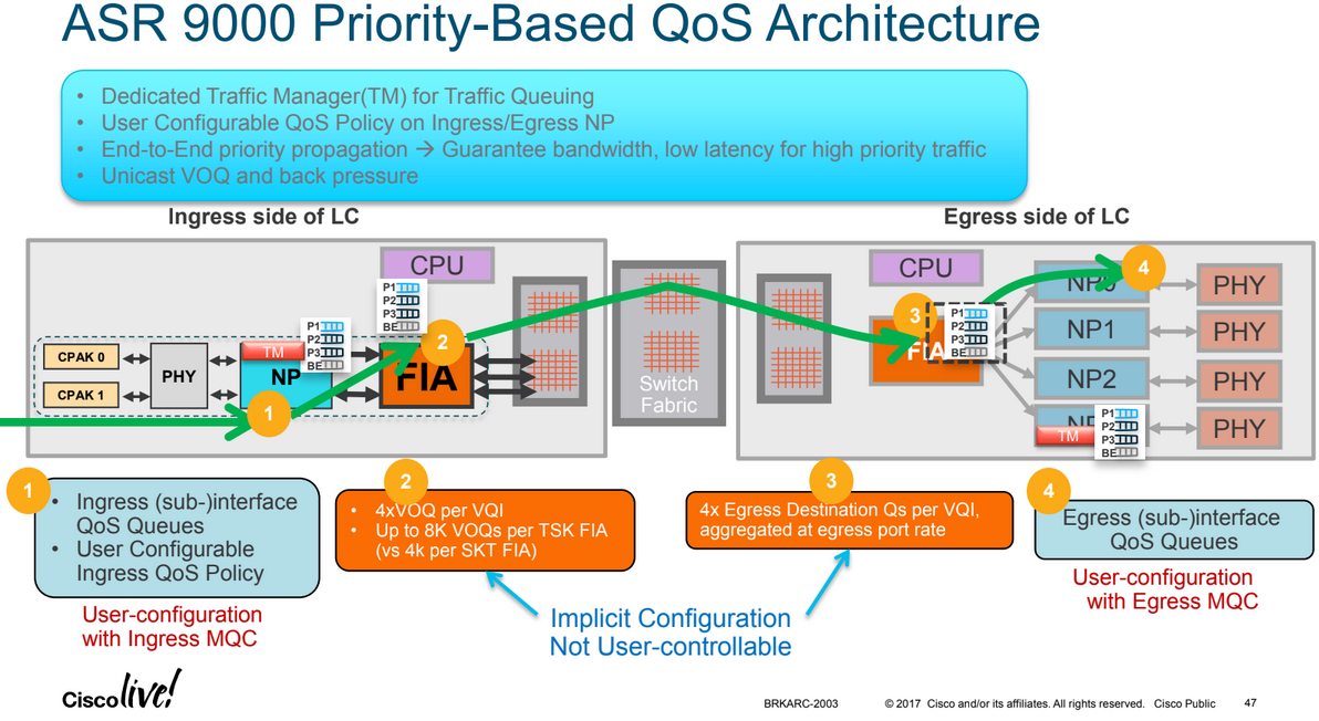
More details here: /index.php?page=asr9000-series-hardware-overview#voq
Every 10G entity in the system is represented in the ingress Fabric Interfacing ASIC (FIA) by a Virtual Output Queue. This means in a fully loaded chassis with 8 line cards, each with 24x 10G ports there are 192 VoQs represented at each FIA of each linecard.
The VOQ's have 4 different priority levels: Priority 1, Priority 2, Default priority and multicast. The different priority levels used are assigned on the packets fabric headers (internal superframe headers) and are set via QOS policy-maps (MQC; modular QoS configuration on the ingress interface).
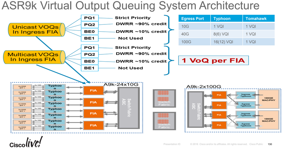
When one defines a policy-map and applies it to a (sub)interface and in that policy map certain traffic is marked as priority level 1 or 2 the fabric headers will reflect that, so that this traffic is put in the higher priority queues of the forwarding ASICs as it traverses the FIA and fabric components.
If one does not apply any QoS configuration, all traffic is considered to be "default" in the fabric queues. In order to leverage the strength of the ASR9000's ASIC priority levels one will need to configure (ingress) QoS at the ports to apply the priority level desired.
A packet classified into a P1 class on ingress is mapped to PQ1 system queue. A packet classified into a P2 class on ingress is mapped to PQ2 system queue. A packet classified into a non-PQ1/2 class on ingress will get mapped to the default/best effort queue along the system QoS path.
Note: The marking is implicit once one assigns a packet into a given queue on ingress; this sets the fabric header priority bits onto the packet, no specific "set" action is required to set the internal fabric header priority value, the priority level is taken from the MQC class configuration.
If one does not configure any service policies for QoS the ASR9000 will set an internal CoS value based on the IP Precedence, 802.1 Priority field or the MPLS EXP bits. Depending on the routing or switching scenario, this internal CoS value could potentially be used to perform marking on newly imposed headers on egress.
For bridged packets on ingress the outermost CoS value would be treated as trusted.
For routed packets on ingress the DSCP/Precedence/outermost EXP value would be treated as trusted based on packet type.
Default QoS will be gleaned from ingress interface before QoS marking is applied on the ingress policy-map.
By default ASR 9000s should never modify DSCP/IP precedence of a packet without a policy-map configured.
Default QoS information should be used for imposition fields only.
In the case of tagged layer 2 traffic arriving at a layer 2 interface like a bridge, VPLS the outer most VLAN tag is mapped to the internal CoS value. The internal CoS value is pushed on at egress to all newly imposed MPLS labels and/or all newly imposed VLAN tags. If the egress is layer 3, the original IPP/DSCP values are still present.
In the case of untagged layer 2 traffic arriving at a layer 2 interface like a bridge, VPLS or VPWS; the internal CoS is set to 0 by default. The internal CoS value (which is 0) is pushed on at egress to all newly imposed MPLS labels and/or all newly imposed VLAN tags. If the egress is layer 3, the original IPP/DSCP values are still present.
In the cased of a layer 3 routed interface ingress, untagged incoming IPP value is mapped to the internal CoS value. The internal CoS value is pushed on at egress to all newly imposed MPLS labels and/or all newly imposed VLAN tags. If the egress is layer 3, the original IPP/DSCP values are still present.
In the case of a tagged layer 3 sub-interface the 802.1p CoS value is ignored and the incoming IPP value becomes the internal CoS value. The internal CoS value is pushed on at egress to all newly imposed MPLS labels and/or all newly imposed VLAN tags. If the egress is layer 3, the original IPP/DSCP values are still present.
In the case of an incoming MPLS interface, weather a VLAN tag is present or not the topmost EXP value is mapped to the internal CoS value. The internal CoS value is pushed on at egress to all newly imposed MPLS labels and/or all newly imposed VLAN tags.
In the case of an MPLS explicit null label, the explicit null EXP is treated the same as a top most non-null label and mapped to the internal CoS.
For ASR9000s running IOS-XR lower than version 6.0.1, when configuring any QoS on a bundle interface the policy is applied to all the member ports of the bundle. This has the caveat that for policers and shapers and the bandwidth command, the configured rate is not a total aggregate. Each LC NP allows its member interface to run up to the configured rate.
The QoS configuration guide for bundled links states the following:
All Quality of Service (QoS) features, currently supported on physical interfaces and subinterfaces, are also supported on all Link Bundle interfaces and subinterfaces. QoS is configured on Link Bundles in the same way that it is configured on individual interfaces. However, the following points should be noted:
- When a QoS policy is applied on a bundle (ingress or egress directions), the policy is applied at each member interface. Any queues and policers in the policy map (ingress or egress directions) will be replicated on each bundle member.
- If a QoS policy is not applied to a bundle interface or bundle VLAN, both the ingress and egress traffic will use the per link members port default queue.
- Link bundle members may appear across multiple Network Processing Units and linecards. The shape rate specified in the bundle policy map is not an aggregate for all bundle members. The shape rate applied to the bundle will depend on the load balancing of the links. For example, if a policy map with a shape rate of 10 Mbps is applied to a bundle with two member links, and if the traffic is always load-balanced to the same member link, then an overall rate of 10 Mbps will apply to the bundle. However, if the traffic is load-balanced evenly between the two links, the overall shape rate for the bundle will be 20 Mbps.
The IOS-XR 6.0.1 release notes include the following statement which indicates that aggregate bundled QoS is supported:
Aggregated Bundle QoS feature allows the shape, bandwidth, police rates and burst values to be distributed between the active members of a bundle, where a QoS policy-map is applied.
The "aggregate-bundle-mode" keword command has been added in IOS-XR 6.0.1 to the existing "hw-module all qos-mode" command. These are the options prior to 6.0.1:
RP/0/RSP0/CPU0:ASR9000(config)#hw-module all qos-mode ?
  ingress-queue-enable       enable ingress queueuing support for MOD-80 4*10G MPA
  per-priority-buffer-limit  set different buffer limit for different priority
  pwhe-aggregate-shaper      Configure pseudo wire headend interface qos parameters
  wred-buffer-mode           Configure L4 WRED accounting mode to buffer mode

6.0.1:
RP/0/RSP0/CPU0:ASR9000(config)# hw-module all qos-mode bundle-qos-aggregate-mode
The new command enables a feature which works as follows:
- Whenever a policy is applied on the bundle member – first a ratio can be calculated based on total bundle bandwidth to bundle member's bandwidth as follows: (ratio = bundle bandwidth/member bandwidth)
- For example if the bundle bandwidth is 20 Gbps with two bundle member bandwidth 10 Gbps, then the reduction will be 2/1 (0.5 * policy rate) for both members.
- With bundle bandwidth 50G (with 10G+40G members) the ratios become 5/1 and 5/4 respectively (it is supporting unbalanced member link speeds).
- The feature will then automatically recalculate the member-port QoS rate whenever a change among bundle occurs. i.e. bundle member active/down/added/removed.
- If traffic is load balanced well among the bundle members, then in aggregate the bundle-ether traffic will be shaped to the policy rate, matching the QoS policy configuration (instead of being members*rate).
- If the traffic is not load-balanced well then a single member link may hit its policer or shaper rate before the others do, and before the traffic flow has reached its totally allowed limit.
- The command takes effect chassis wide, it can't be enabled/disabled per bundle.
- When the aggregated bundle mode changes, QoS polices on bundle (sub)interfaces are modified automatically.
- Reloading line card is not required.
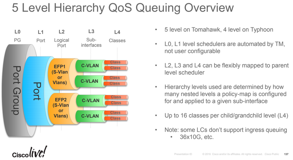
The ASR 9000 traffic manager (TM) for the enhanced Ethernet line cards supports up to 16 Queues. This was extended from 8 queues to 16 queues at the leaf level called L4 in a QoS policy. The L3, L4 service profiles in 16 Q-mode are similar to that of the 8 Q-mode, just with an increase in the number of normal priority queues.
The capabilities of each mode are:
8 Q-mode: 8 L4 flows per L3 class. Up to 32000 L3 classes in TM.
16 Q-mode: 16 L4 flows per L3 class. Up to 16000 L3 classes in TM.
The support for 16 queues has these restrictions:
Supported only on the enhanced Ethernet line cards.
When 16 Q-mode policy is applied on all interfaces, the interface scale number will be 4K interfaces.
All -TR cards have 8 input and 8 output queues by default (e.g. A9K-8X100G-TR or A9K-48X10G-TR etc.). This means that on an 8 port card (e.g. A9K-8X100G-TR) there is 64 input and 64 output queues whereas on a 48 port card (e.g. A9K-48X10G-TR) there are 384 input and 384 output queues. The Traffic Manager is the same on both of these example cards as they both use Tomahawk NPUs (the TM is inside the NPU and there is one per NPU). This means that the most commonly encountered limit to the -TR line cards is the per-port queue limit rather than the overall line card QoS scale.
NPU speed per port buffer:
Trident L and B cards support 17M PPS (~15Gbps) and 50ms per-port-buffers.
Trident E cards support 17M PPS (~15Gbps) and 150m per-port-buffers.
Typhoon SE cards support 44M PPS (~60Gbps) and 339ms per-port-buffers when there are 2 ports-per-NPU.
Typhoon TR cards support 44M PPS (~60Gbps) and 170ms per-port-buffers when there are 2 ports-per-NPU.
Typhoon SE cards support 44M PPS (~60Gbps) and 226ms per-port-buffers when there are 3 ports-per-NPU.
Typhoon TR cards support 44M PPS (~60Gbps) and 113ms per-port-buffers when there are 3 ports-per-NPU.
Tomahawk TR cards support 6Gbps and 100ms per-port buffers.
Tomahawk SE cards support 12Gbps and 200ms per-port buffers.
Trident NPUs support 32k egress queues and 32k ingress queues on the 10G line cards.
Trident NPUs support 64k egress queues and 32k ingress queues on the 40x1G line cards.
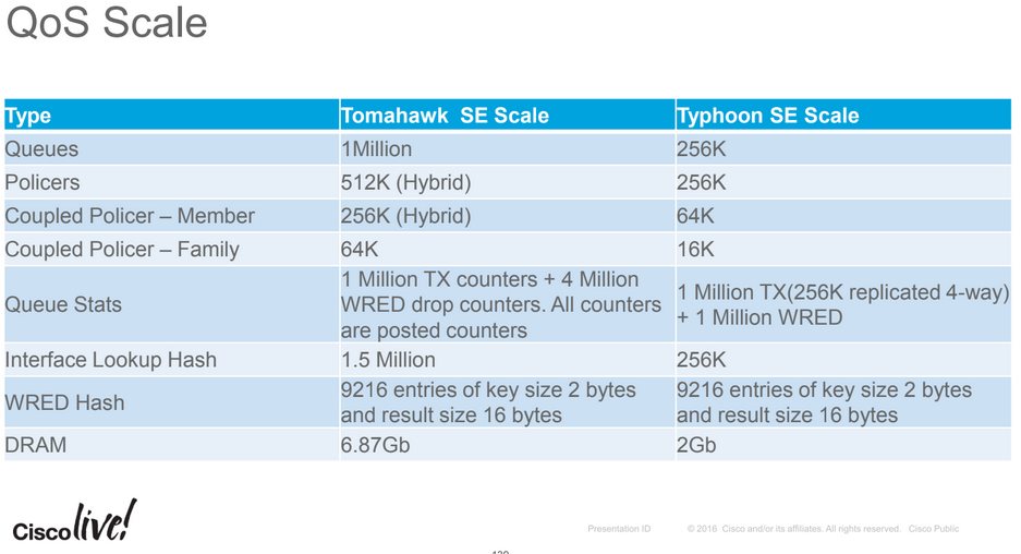
Typhoon NPUs support 192k egress queues and 64k ingress queues (SE cards).
Tomahawk TR cards supports 8 queues per-port.
Tomahawk SE cards support 1M queues, 4M queues for 800G line card.
Trident NPUs support up to 64k policers (per NPU) on the E series line cards, 16k on the B series line cards and 8k policers on the L series cards.
Typhoon NPUs support up to 256k policers (per NPU) on the SE series line cards and 8k policers (per NPU) on the TR line cards.
Tomahawk NPUs support up to 512k policers (per NPU) on SE cards and 32k policers (per NPU) for TR line cards.
Trident line cards support 4K L3 sub-interfaces per NPU.
Typhoon TR line cards support 8K L3 sub-interface per NPU and SE line cards support 20K per NPU.
Tomahawk TR line cards support 8k L3 sub-interfaces per NPU and SE cards support 64K per NPU.
When using breakout interfaces, e.g. SR10 or LR10, the 10x10Gbps interfaces share the NPU limits. For example, an A9K-100G-TR card has 2x100G interfaces per NPU. If one port was split into 10X10G ports or both to form 20x10G ports, the 8K L3 sub-interface limit / 32k policer limit, it shared across all 1x100 + 10x10G ports or 2x10G ports.
With regards to scaling policers, if the policer only contains a single queue (class-default), policers applied to an interface don't instantiate additional queues on that port. This means that single class (class-default) policers aren't limited to the 8 input or 8 output queue limits of an interface (e.g. it is possible to have more than 8 sub-interfaces on a -TR line card, each with a single-class policer per physical port, even though -TR cards are limited to 8 in + 8 out queues per physical port).
The Typhoon Traffic Manager can support up to 70Gbps of traffic half-duplex. When queueing is enabled in certain line cards the TM is oversubscribed. In the 24x10GE Typhoon line-card, there are 8 NPUs and each NP maps to 3x10GE ports. This means a maximum of 60Gbps half duplex can be passed through the Typhoon TM which is less than the 70Gbps limit. For some higher bandwidth Typhoon line cards the TM is unable to support the bidirectional line-rate requirements of the physical ports. In such a case the TM is bypassed in the ingress direction (from physical ports towards chassis fabric) to achieve line rate forwarding. In the 36X10GE Typhoon line card there are 6 NPUs. Each NPU controls 6x10GE ports. In the ingress path (towards the chassis fabric) the Traffic-Manager is bypassed. The Traffic Manager is only used in the egress direction (towards the ports). This limits the total traffic passing through the TM to 60Gbps. In 100G Typhoon line-cards (e.g. 1x100GE and 2x100GE), there are two NPUs per 100G port. In 100G mode TMs from two NPs are combined to act as one, thereby increasing the TM throughput to 100G. Since the ingress NPU's TM is being used by the egress NP only egress queuing is supported on Typhoon 1x100G and 2x100G cards. The Tomahawk TM runs at the NPU line rate (240Gbps) meaing that Tomahawk cards have no limitations in relation to queueing throughoput.
ASR9001 (MOD80-SE / Typhoon NPU) specifics:
ASR9001s use a built-in MOD80-SE which has 2GBs of packet buffers, ASR9001s support 256k policers per NPU.
RP/0/RSP0/CPU0:abr1#show qos capability location 0/0/CPU0
Capability Information:
======================

Max Policy maps supported on this LC: 16384
Max policy hierarchy: 3
Max policy name length: 64
Max classes per child-policy: 1024
Max classes per policy: 1024
Max classes per grand-parent policy: 1
Max police actions per class: 2
Max marking actions per class: 2
Max matches per class : 8
Max class-map name length: 64
Max members in a bundle: 64
Max instance name length: 32
General Checks:
"show drops all location all"
"show drops"
"show asic-errors all location 0/0/CPU0"
"show asic-errors all location 0/RSP0/CPU0"
Look for active PFM alarms on LC as well as RSP:
"show pfm location all"
Check FPGA Software Is Updated:
"show controllers np summary all"
"admin show hw-module fpd location all"
Check Hardware Diagnostics:
"admin show diagnostic result location all"
Clearing Counters:
"clear counters all"
"clear controller np counters all"
"clear controller fabric fia location"
"clear controller fabric crossbar-counters location"
Checking Interface Stats:
"show interface Gi0/0/0/0 | inc rate" ! Note that this will exclude Ethernet headers and include payload only
Check LC NP Stats:
"sh controller np ports all loc 0/0/cpu0"
"show controllers pm vqi location all"
"show controllers pm interface Te0/0/0/0"
"show controllers pm location 0/0/CPU0 | i "name|switch"
"show controllers np fabric-counters all all"
Some interesting counters for this command are:
xaui_a_t_transmited_packets_cnt -- Num pkt sent by NPU to bridge
xaui_a_r_received_packets_cnt -- Num pkt sent by bridge to NPU
When using "show controllers np fabric-counters all all location 0/0/CPU0", all zero counts can be an indication there are Tx/Rx problems between the NP and FIA.
"show controllers np counters all"
Some interesting counters for this command are:
800 PARSE_ENET_RECEIVE_CNT -- Num of packets received from external interface
970 MODIFY_FABRIC_TRANSMIT_CNT -- Num of packets sent to fabric
801 PARSE_FABRIC_RECEIVE_CNT -- Num of packets received from fabric
971 MODIFY_ENET_TRANSMIT_CNT -- Num of packets sent to external interface
When using "show controller np counters all loc 0/0/CPU0" the output "No non-zero data counters found" for an NP can be an indication it has locked up.
Check LC FIA & Bridge Stats:
"show controllers fabric fia link-status location 0/0/CPU0"
"show controllers fabric fia stats location 0/0/CPU0"
"show controllers fabric fia q-depth location 0/0/CPU0"
"show controllers fabric fia drops ingress location 0/0/CPU0"
"show controllers fabric fia drops egress location 0/0/CPU0"
"show controllers fabric fia errors ingress location 0/0/CPU0"
"show controllers fabric fia errors egress location 0/0/CPU0"
"show controllers fabric fia bridge *" Trident LC Only
Check RSP Abriter and Xbar Stats:
"show controllers fabric arbiter serders location ..."
"show controllers fabric crossbar link-status instance 0 location 0/RSP0/CPU0"
"show controllers fabric crossbar link-status instance 1 location 0/RSP0/CPU0"
"show controllers fabric crossbar statistics instance 0 location 0/RSP0/CPU0"
"show controllers fabric ltrace crossbar last 100 location all"
Check how the interface policy is applied in hardware:
"show qos capability location 0/0/cpu0"
"show qos interface Te0/0/2/1 output"
"show policy-map interface Te0/0/2/1 output" ! Note that this will inlcude Ethernet SA+DA+ETYPE+VLANS+PAYLOAD+CRC
"show qoshal resource summary location 0/0/CPU0"
"show qoshal default-queue interface Te0/0/2/1"
Previous page: 6500/7600 QoS Troubleshooting
Next page: CPE Hierarchical QoS Framework (over DSL)